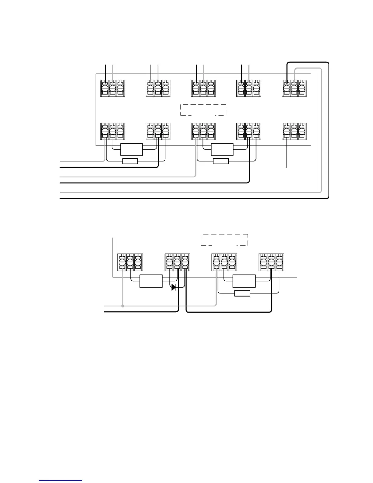
4
• Note 1: This component is the fire resistor. Its value is specified by the Fire Control Panel manufacturer. For U.S.
installations it is typically a short circuit
• ALWAYS use a separate 2-core cable for each Receiver head
• CAUTION: For system monitoring - Do not use looped wire under any terminals. Break wire run to provide
monitoring of connections
• Components not supplied:
• Schottky Diode - Typically 60V, 1A (UL-rated for installations conforming to NFPA 72)
• End Of Line ('EOL') component - supplied by Fire Control Panel manufacturer
• Fire Resistor not supplied
• After installation, check operation of Fire and Fault connection on Fire Panel
1.2 Wiring Diagram
RECEIVER 1
O
UTPUT
+ -
R
ECEIVER 2
OUTPUT
+
-
T
RANSMITTER
SUPPLY
+
-
T
RANSMITTER
SUPPLY
+
-
12V to 36V DC
RECEIVER 1
FIRE
N/O COM N/C
RECEIVER 1
FAULT
N/O COM N/C
RECEIVER 2
FIRE
N/O COM N/C
RECEIVER 2
FAULT
N/O COM N/C
R
ECEIVER 1
FIRE
N
/O COM N/C
R
ECEIVER 1
FAULT
N
/O COM N/C
RECEIVER 2
F
IRE
N/O COM N/C
RECEIVER 2
FAULT
N
/O COM N/C
ZONE -
ZONE +
see note 1
see note 1
EOL
s
ee note 1
EOL
see note 1
EOL
EXTERNAL
RESET
EXTERNAL
R
ESET
Z
ONE 1 -
ZONE 1 +
ZONE 2 -
ZONE 2 +
SUPPLY -
SUPPLY +
For connection of both Receivers to one zone:
For connection of Receivers to individual zones: