24
This setting controls whether the System Controller Status LED will
flash.
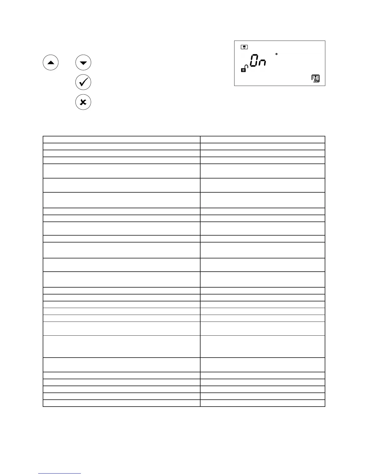
7.3.3 Controller Status LED ON/OFF Screen
Toggle ON or OFF
Confirm setting
Abort change
OR
8. Specification
Parameter Value
Operating Range: 5 to 120m
Operating Voltage Range: 12 to 36V DC +/- 10%
Transmitter Current: 8mA
Quiescent Current (Controller with 1 or 2 Receivers): 14mA
Alarm Current (Controller with 1 or 2 Receivers): 14mA
Fault Current (Controller with 1 or 2 Receivers): 14mA
Power Down Reset Time: >20 seconds
Fire and Fault Relay Contacts: VFCO 2A@ 30 Volts DC, resistive
Operating Temperature:
-10°C to +55°C (non-condensing)- EN
-20°C to +55°C (non-condensing)- UL
Storage Temperature: -40°C to +85°C (non-condensing)
Receiver Tolerance to Beam Misalignment at 25% sensitivity: +/- 2.5%
Transmitter Tolerance to Beam Misalignment at 25% sensitivity: +/- 0.7%
Fire Alarm Thresholds:
Selectable increments of 1% from 10% to 60%.
Major selectable increments are 25, 35 and 50%
Delays to Fire and Fault: 2-30s, individually selectable
Optical Wavelength: 850nm
Control Unit Dimensions: 203 x 124 x 73mm (W x H x D)
Transmitter & Receiver Dimensions: 74 x 74 x 161mm (W x H x D)
Weight (Control Unit): 606g
Weight (Transmitter & Receiver inc. brackets): 207g
LED Indications - Control Unit:
Red = Fire (one for each Receiver)
Amber = Fault (one for each Receiver)
Green = System OK
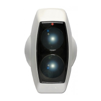
LED Indications - Receiver:
Red = Fire. Green and Amber indication LEDs for
single-person alignment
IP Rating: IP54
Relative Humidity (Max.): 93%, (non-condensing)
CPD Reference: TBC
UL File: S3417 (volume 6)
Housing Construction (Controller/Transmitter/Receiver): UL94 V0 PC