Type 2500
13
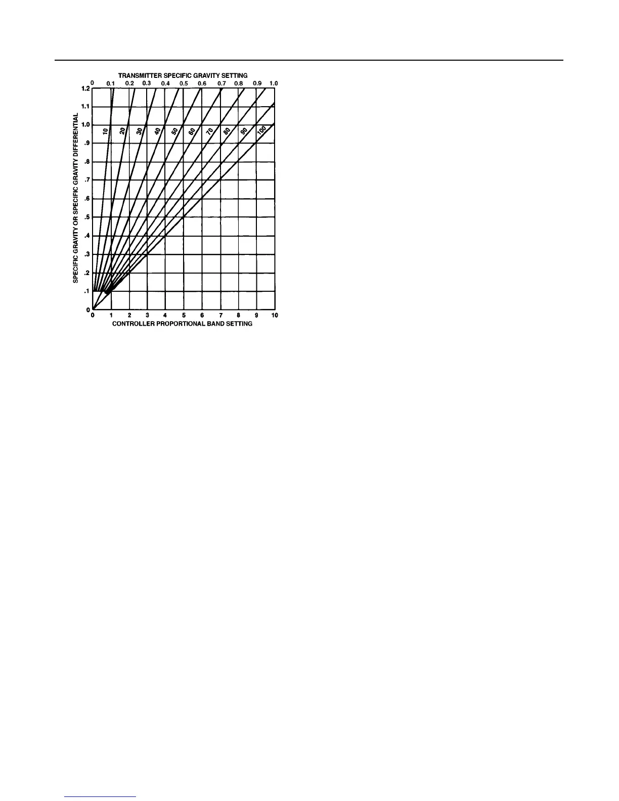
Figure 13. Proportional Band and Specific Gravity
Setting Chart (chart assumes standard wall torque tube and
displacer volume in table 2)
NOTE:
EACH CURVE MARKED WITH PERCENTAGE OF DISPLACER USED.
1C9259–G
A3891–1/IL
Type 2500 Controller or 2500T
Transmitter
Note
In the following steps the output pres-
sure can go as high as the controller
supply pressure.
1. Turn on the supply pressure and check that the
supply pressure gauge reads 20 psig (1.4 bar) for a 3
to 15 psig (0.2 to 1 bar) or 35 psig (2.4 bar) for a 6 to
30 psig (0.4 to 2 bar) output pressure range. If the
pressure is incorrect, loosen the locknut of the Type
67FR filter/regulator (figure 11); turn the adjusting
screw clockwise to increase the pressure or, counter-
clockwise to decrease the pressure. Tighten the lock-
nut after setting the regulator pressure.
2. Set the process variable to its minimum value.
3. Make sure that the PROPORTIONAL BAND or
SPECIFIC GRAVITY control is at the setting deter-
mined earlier in this section. Then, set the RAISE
LEVEL or ZERO ADJUSTMENT control at an ap-
propriate value according to table 4. This table gives
recommended settings based on maximum and mini-
mum possible PROPORTIONAL BAND and SPECIF-
IC GRAVITY settings. If an intermediate PROPOR-
TIONAL BAND or SPECIFIC GRAVITY setting is
necessary, extrapolation may be used to determine an
appropriate RAISE LEVEL or ZERO ADJUSTMENT
setting.
Note
The raise level dial does not reflect actu-
al fluid level in the tank or fluid level
position on the displacer.
4. The OUTPUT gauge on a 3 to 15 psig (0.2 to 1
bar) range should read 3 psig (0.2 bar) for direct or 15
psig (1 bar) for reverse action. On a 6 to 30 psig (0.4
to 2 bar) range the OUTPUT gauge should read 6 psig
(0.4 bar) for direct or 30 psig (2 bar) for reverse action.
5. On a controller or transmitter with a mechanical
indicator assembly, the pointer should be over the
LOW point on the indicator plate. If a slight adjustment
is necessary, loosen the side hex clamp nut (key 40,
figure 19), shift the pointer, and retighten the nut.
6. Increase the process variable to the level desired
for full output change. The OUTPUT gauge on a 3 to
15 psig (0.2 to 1 bar) range should read 15 psig (1
bar) for direct or 3 psig (0.2 bar) for reverse action. On
a 6 to 30 psig (0.4 to 2 bar) range the OUTPUT gauge
should read 30 psig (2 bar) for direct or 6 psig (0.4
bar) for reverse action. On a controller or transmitter
with an indicator assembly, the pointer should be over
the HIGH point on the indicator plate; slight plate ad-
justment may be necessary, as described at the end
of step 5.
7. If all prestartup checks are satisfactory, go to the
startup procedure. If performance is unsatisfactory,
proceed to the Calibration section.
Type 2500S Controller
Note
In the following steps the output pres-
sure can go as high as the controller
supply pressure.
1. Turn on the supply pressure and check that the
SUPPLY pressure gauge reads 20 psig (1.4 bar) for a
0 to 20 psig (0 to 1.4 bar) output pressure range or 35
psig (2.4 bar) for a 0 to 35 psig (0 to 2.4 bar) output
pressure range. If the pressure is incorrect, loosen the
locknut of the Type 67FR filter/regulator (figure 11);
turn the adjusting screw clockwise to increase the
pressure or counterclockwise to decrease pressure.
Tighten the locknut after setting the pressure.
2. Set the process variable to its minimum value.
3. On a controller with a mechanical indicator assem-
bly, the pointer should be over the LOW point on the
indicator plate. If a slight adjustment is necessary,
loosen the hex clamp nut (key 40, figure 19), shift the
pointer and retighten the nut.
 Loading...


