Type 2500
17
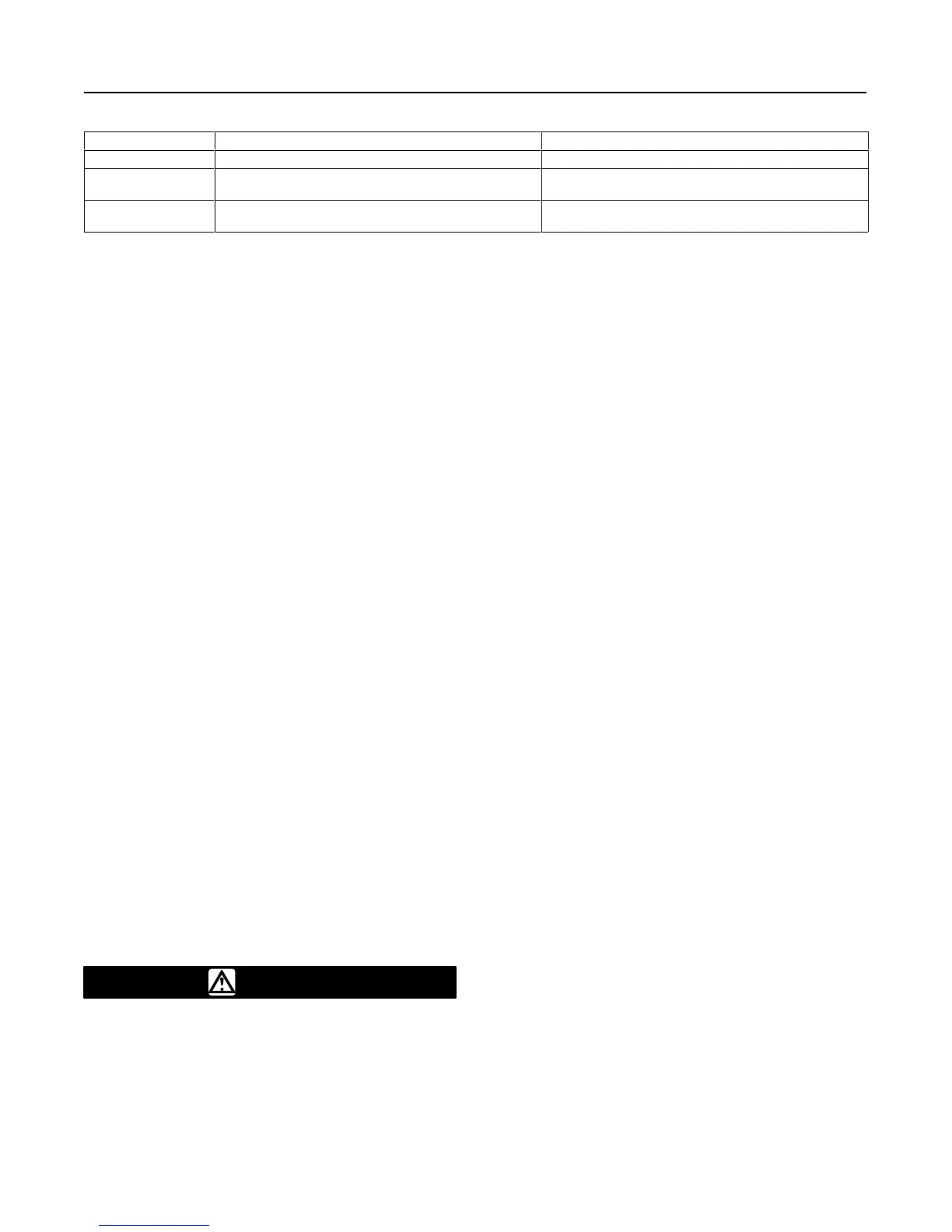
Table 5. Minimum and Maximum Limits for Setting Process Variables
APPLICATION MINIMUM LIMIT MAXIMUM LIMIT
Liquid Level Displacer must be completely out of liquid Displacer must be completely submerged in liquid
Interface Displacer must be completely submerged in lighter of two
process liquids
Displacer must be completely submerged in
heavier of two process liquids
Density Displacer must be completely submerged in liquid having
specific gravity of lowest range point
Displacer must be completely submerged in liquid having
specific gravity of highest range point
0.0361 = Weight of one cubic inch of water
(specific gravity = 1.0), in pounds.
V
= Volume, in cubic inches, of the portion
of the dis
-
placer submerged. Or,
V = (π/4) (displacer diameter)
2
(length of displacer
submerged)
SP
GR = Specific gravity of
the process fluid at operating
temperature.
For interface level measurement, the equation be-
comes:
W
s
+ W
d
–[(0.0361)(V
t
)(SP GR
l
)
) (0.0361)(V
h
)(SP GR
h
* SP GR
l
)]
where:
V
t
= Total volume, in cubic inches, of the displacer.
SP
GR
l
= Specific gravity of the lighter of the fluids at oper
-
ating temperature.
V
h
= Volume, in cubic inches, of the portion of the
displacer submerged in the heavier of the
fluids.
Or,
V
=
(π
/4) (displacer diameter)
2
(length
of the displac
-
er submerged)
SP
GR
h
= Specific gravity of the heavier
of the fluids at op
-
erating temperature.
Calibration Procedure
WARNING
The following calibration procedures
require taking the controller/transmitter
out of service. To avoid personal injury
and property damage caused by an un-
controlled process, provide some tem-
porary means of control for the process
before taking the controller/transmitter
out of service.
Figure 12 shows adjustment locations, except as
otherwise indicated. In order to calibrate, open-loop
conditions must exist. One way to obtain an open loop
is to ensure that there is no flow through the final con-
trol element. Another way to obtain an open loop is to
disconnect the controller/transmitter output signal line
and plug the output connection with a test pressure
gauge.
Several steps in these calibrating procedures require
setting the process variable at its minimum and maxi-
mum limits, according to table 5.
Note
If the process cannot be varied readily
or the Wet Calibration method cannot be
used in the following steps, be sure to
use the proper sequence of correct
weights as found in the Determining
Amount of Suspended Weight proce-
dure. Whenever the following steps re-
quire particular prestartup checks, refer
to the appropriate procedures for: Type
2500 Controller or 2500T Transmitter,
Type 2500S Controller, or Type 2503
Controller.
Type 2500 Controller and 2500T
Transmitter
1. Turn on the supply pressure and check that it is set
according to the appropriate prestartup checks proce-
dure.
2. Make sure that the PROPORTIONAL BAND or
SPECIFIC GRAVITY adjustment is at the setting de-
termined according to the appropriate prestartup
check procedure.
3. Adjust the RAISE LEVEL (Type 2500) or ZERO
ADJUSTMENT (Type 2500T) to the appropriate value
per table 4. This table gives recommended settings
based on maximum and minimum possible PROPOR-
TIONAL BAND (Type 2500) or SPECIFIC GRAVITY
(Type 2500T) settings. If an intermediate PROPOR-
TIONAL BAND or SPECIFIC GRAVITY setting is nec-
essary, extrapolation may be used to determine a new
RAISE LEVEL or SPECIFIC GRAVITY setting.
 Loading...


