Quick Start Guide
D103203X012
DVC2000 Digital Valve Controller
July 2017
11
If the process and ambient temperatures exceed the limits indicated by zone 2, then the DVC2000 high temperature mounting kit
can not be used. If temperatures exceed zone 2, you must use an extension bonnet or bracket mounted instrument.
1. Isolate the control valve from the process line pressure and release pressure from both sides of the valve body. Shut
off all pressure lines to the actuator, releasing all pressure from the actuator. Use lock‐out procedures to be sure
that the above measures stay in effect while you work on the equipment.
2. For the GX actuator, identify the yoke side to mount the DVC2000 digital valve controller based on the actuator fail
mode. Refer to the GX Control Valve and Actuator System instruction manual (D103175X012
).
3. Loosely attach the feedback pieces and magnet assembly to the valve stem connector. Do not tighten the fasteners
because fine adjustment is required.
CAUTION
Do not install a magnet array that is shorter than the physical travel of the actuator. Loss of control will result from the
magnet array moving outside the range of the index mark in the feedback slot of the DVC2000 housing.
4. Using the alignment template (supplied with the mounting kit), position the feedback array inside the retaining
slot.
5. Align the magnet array as follows:
D For air‐to‐open 667 size 30i - 76i and GX actuators vertically align the magnet array so that the center line of the
alignment template is lined up as close as possible with the upper
extreme of the valid travel range on the feedback
array. See figure 10.
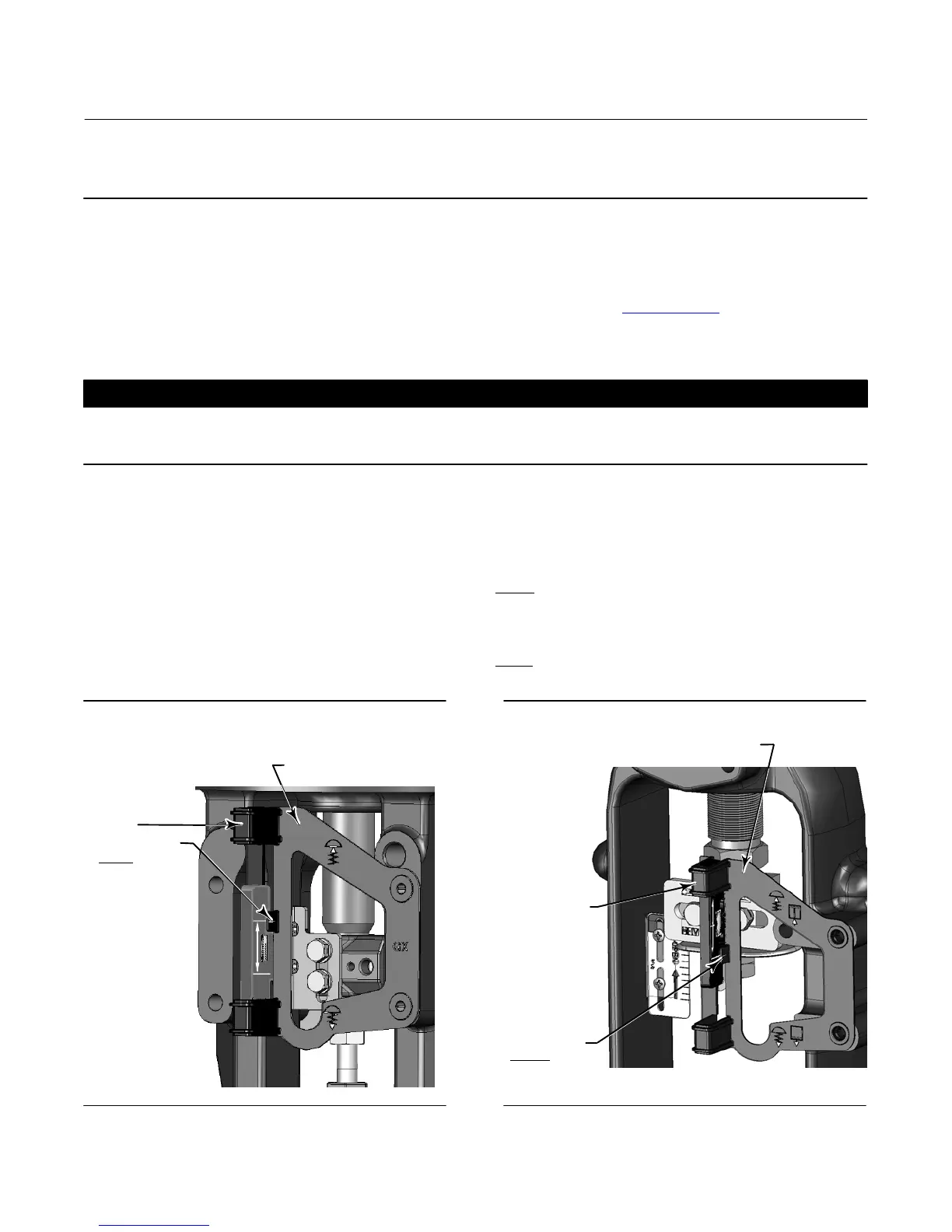
D For air‐to‐close 657 size 30i -70i and GX actuators vertically align the magnet array so that the center line of the
alignment template is lined up as close as possible with the lower
extreme of the valid travel range on the feedback
array. See figure 11.
LINE UP WITH
UPPER
EXTREME
OF VALID TRAVEL
RANGE
Figure 10. Air‐to‐Open Magnet Array Alignment
ALIGNMENT TEMPLATE
RETAINING
SLOT
Figure 11. Air‐to‐Close Magnet Array Alignment
LINE UP WITH
LOWER
EXTREME
OF VALID TRAVEL
RANGE
ALIGNMENT TEMPLATE
RETAINING
SLOT
 Loading...


