Quick Start Guide
D103203X012
DVC2000 Digital Valve Controller
July 2017
12
6. Tighten the fasteners and remove the alignment template. Continue on with the appropriate step 7 below.
Note
Use a flat end hex key to tighten the magnet assembly fasteners to a torque of 2.37 N•m (21 in•lbf) for 4 mm screws, and
5.08 N•m (45 in•lbf) for 5 mm screws. For added security, especially in vibrating services, blue (medium) threadlocker may be
used on the fasteners.
For Air‐to‐Open Actuators (667 size 30i - 76i and GX)
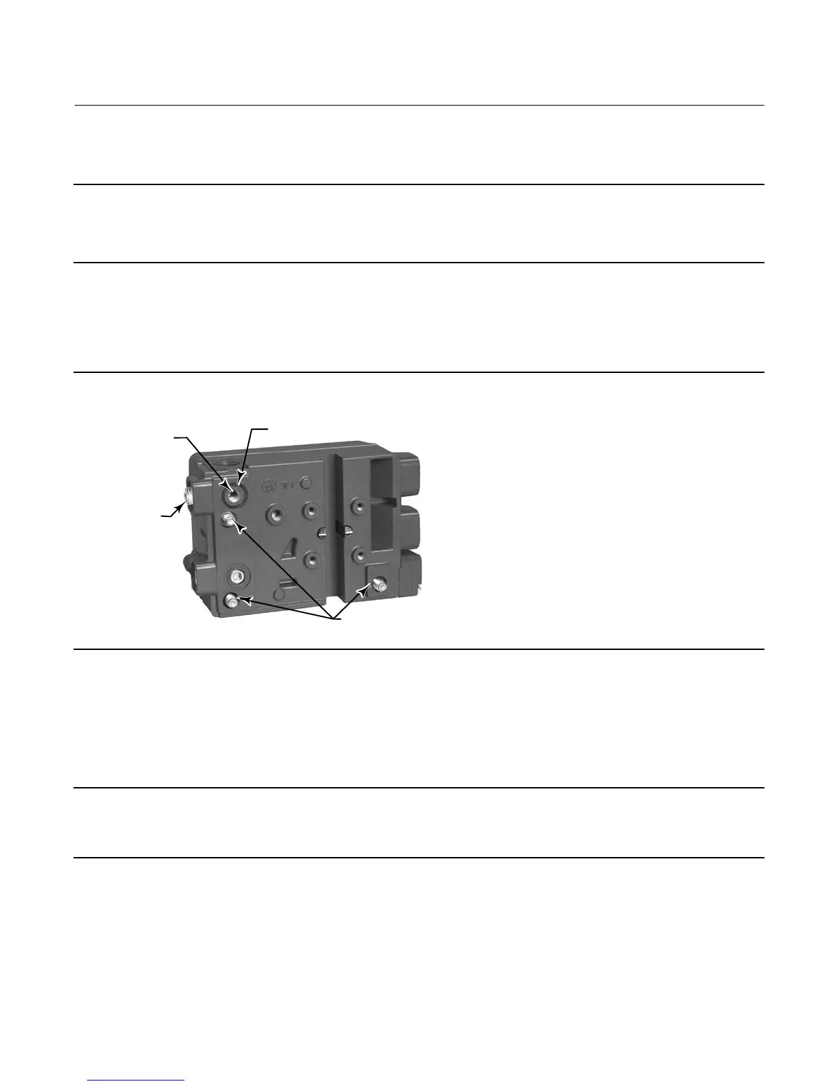
7. Remove the top plug (R1/8) from the back of the DVC2000 housing. This pneumatic output port on the DVC2000
lines up with the integral actuator pneumatic port. See figure 12.
Figure 12. Modifications for Integral Mounted Actuator - Air‐to‐Open Construction Only
W9019
REMOVE THE
R1/8 PLUG
ADD THE 1/4 NPT
OR G1/4 PLUG
INSTALL THE O‐RING BEFORE
ASSEMBLING TO THE ACTUATOR
M8 MOUNTING BOLTS
FOR GX HOUSING ONLY
8. Install the plug (either G1/4 or 1/4 NPT, included in the mounting kit) in the external output pneumatic port.
9. Remove the cover of the digital valve controller.
10. Attach the digital valve controller to the actuator mounting pad on the side that has the open pneumatic port. Be
sure to place the O‐ring between the digital valve controller's pneumatic output and the actuator mounting pad.
Pneumatic tubing is not required because the air passages are internal to the actuator.
Note
Use a 6 mm hex key to attach the digital valve controller the GX actuator mounting pad.
Use a 13 mm socket or box end wrench to attach the digital valve controller to the 667 size 30i -76i actuator mounting pad.
11. Check for clearance between the magnet assembly and the DVC2000 feedback slot. The magnet assembly should
be positioned so that the index mark in the feedback slot of the DVC2000 housing is within the valid range on the
magnet assembly throughout the range of travel. See figure 2.
 Loading...


