Quick Start Guide
D103203X012
DVC2000 Digital Valve Controller
July 2017
16
The digital valve controller is normally powered by a control system output card. The use of shielded cable will ensure
proper operation in electrically noisy environments. Wire size requirements are 14 AWG maximum, 26 AWG
minimum.
Be sure to follow the appropriate I.S. circuit guidelines when installing field wiring to the loop terminals as well as the
limit switch and transmitter terminals.
Wire the digital valve controller as follows:
1. Remove the main instrument cover.
2. Route the field wiring into the terminal box through the conduit connection. When applicable, install conduit using
local and national electrical codes that apply to the application.
3. Connect the control system output card positive wire “current output” to the +11 terminal. Connect the control
system output card negative (or return) wire “current output” to the -12 terminal.
4. Two ground terminals are available for connecting a safety ground, earth ground, or drain wire. These ground
terminals are electrically identical. Make connections to these terminals following national and local codes and
plant standards.
5. Replace the cover if the local interface is not being used for configuration or calibration.
Options Boards
All three options circuits (transmitter, switch 1 and switch 2) control current from an external power source similar to
the operation of a 2‐wire transmitter.
Limit Switches
On units that are supplied with integral limit switches, additional terminals provide the field wiring connection point.
The limit switches are isolated from each other and from the digital valve controller's primary feedback. If only one
switch is to be used, you must use channel 1. Although electrically isolated per Intrinsic Safety requirements, channel 2
derives its power from channel 1. Therefore channel 2 cannot be used alone.
Wire the limit switches as follows:
1. Remove the main instrument cover.
2. Route the field wiring into the terminal box through the conduit connection. When applicable, install conduit using
local and national electrical codes that apply to the application.
3. Connect the control system input card positive wire “switch input” to the +41 terminal. Connect the control system
input card negative wire “switch input” to the -42 terminal. Refer to figure 15.
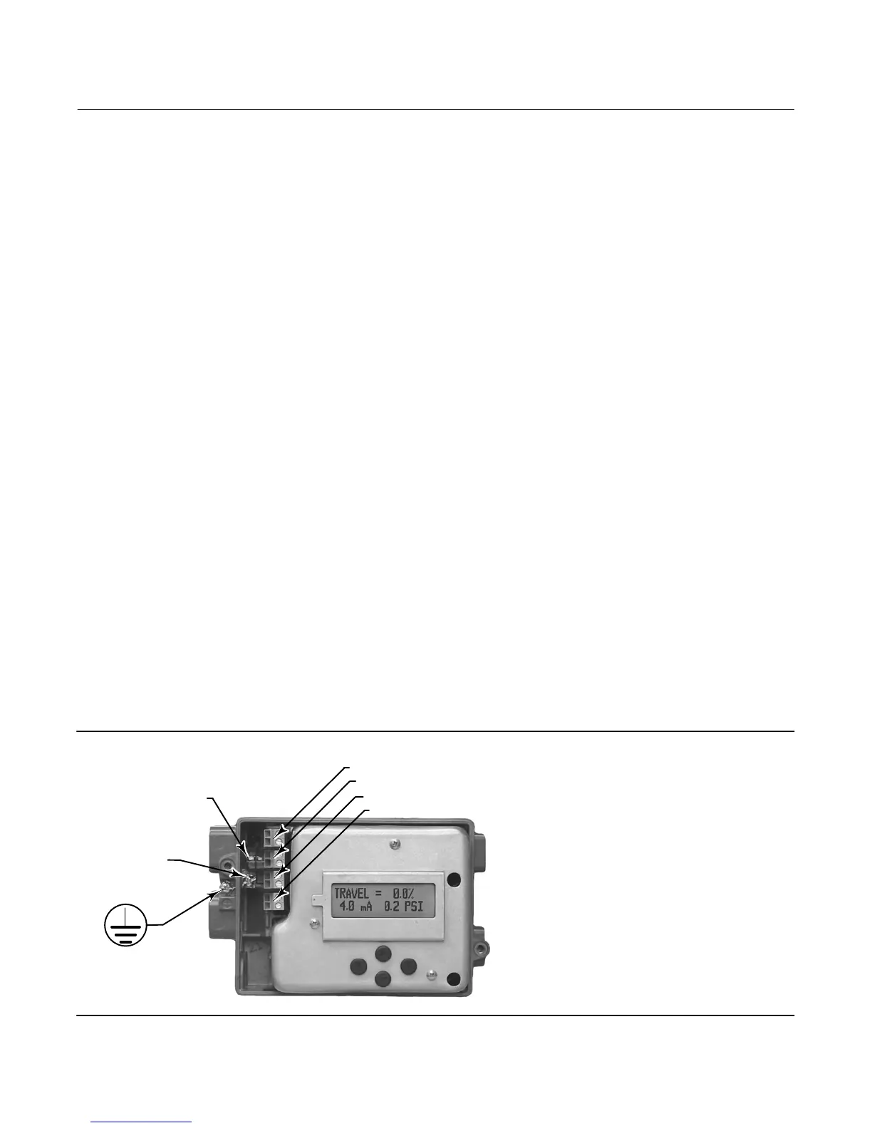
HART COMMUNICATION
TERMINATION POINTS
+31/ -32 (TRANSMITTER)
+11/ -12 (LOOP)
+41/ -42 (SWITCH 1)
+51/ -52 (SWITCH 2)
W8838
Figure 15. Loop, Transmitter, and Limit Switch Terminals
EARTH
GROUND
INTERNAL
GROUND
 Loading...


