Quick Start Guide
D103203X012
DVC2000 Digital Valve Controller
July 2017
25
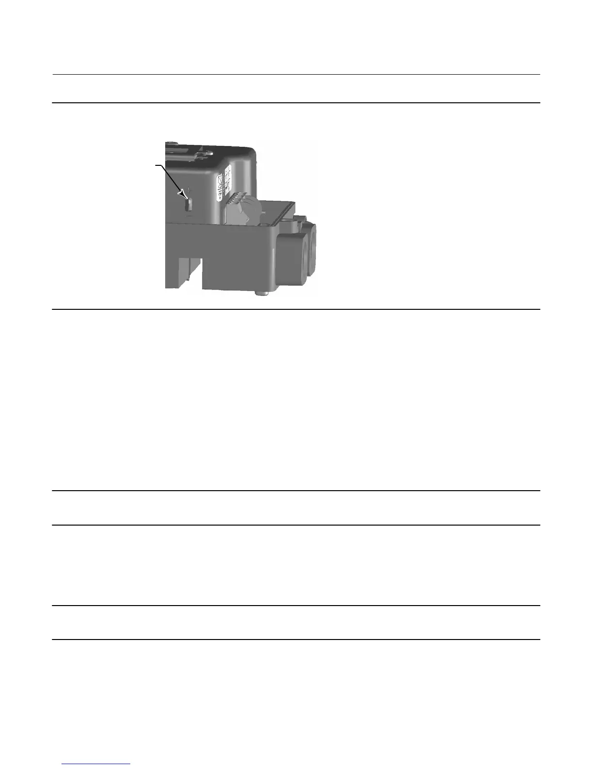
Figure 21. XMTR Switch
TRANSMITTER SWITCH
FOR FAIL SIGNAL
+ HIGH (SHOWN) OR
-LOW
W8839
Switch #1 Trip Point—Defines the threshold for the limit switch wired to terminals +41 and -42 in percent of calibrated
travel.
Switch #1 Closed—Configures the action of the limit switch wired to terminals +41 and -42. Selecting ABOVE
configures the switch to be closed when the travel is above the trip point. Selecting BELOW configures the switch to be
closed when the travel is below the trip point. Selecting DISABLED removes the icons and status from the display.
Switch #2 Trip Point—Defines the threshold for the limit switch wired to terminals +51 and -52 in percent of calibrated
travel.
Switch #2 Closed—Configures the action of the limit switch wired to terminals +51 and -52. Selecting ABOVE
configures the switch to be closed when the travel is above the trip point. Selecting BELOW configures the switch to be
closed when the travel is below the trip point. Selecting DISABLED removes the icons and status from the display.
Note
Switch #2 is only operational if power is applied to switch #1 also. Switch #2 cannot be used alone.
Position Transmitter Calibration
Note
This procedure will not move the control valve. The instrument will simulate an output for calibration purposes only.
This procedure is only available on units that have the optional position transmitter hardware installed. The DVC2000
digital valve controller is shipped from the factory with the position transmitter already calibrated. You do not
normally need to perform this procedure. However, if you suspect that this needs adjustment, follow the procedure
below and refer to figure 22.
 Loading...


