Quick Start Guide
D103203X012
DVC2000 Digital Valve Controller
July 2017
27
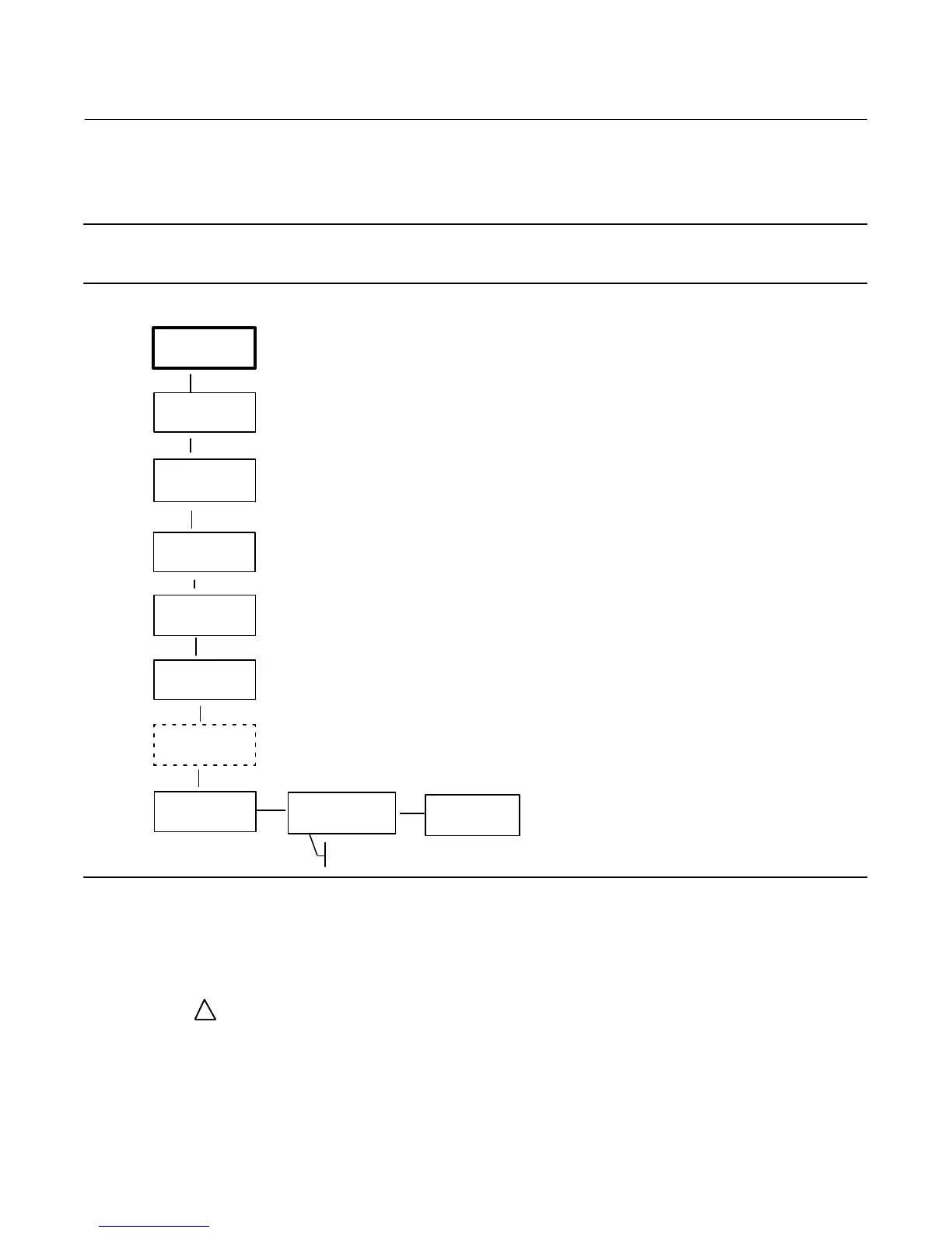
The UP (Y) and DOWN (B) arrow keys will allow you to change the setpoint and therefore move the valve manually.
To exit the manual mode, use the LEFT (A) arrow key to return to the choice list. Select ANALOG.
Note
When placing the instrument back into ANALOG, the valve will step back to the position commanded by the input current.
Figure 23. Local Control
TUNING
TRAVEL = 66.8%
14.6 MA 0.92 BAR
QUICK SETUP
Y
B
Y
B
Y
B
TRAVEL
CALIBRATION
Y
B
DETAILED SETUP
ANALOG
MANUAL
MANUAL SP = XX
TRAVEL = XX.X
"
CONTROL
ANALOG
Y
B
POSITION
TRANSMIITTER CAL
"
A
Y
B
ANALOG INPUT
CALIBRATION
LOCAL
CONTROL
B
Y
Only with Optional Position
Transmitter / Limit Switches
Diagnostic Messages, Codes and Details
The DVC2000 digital valve controller is constantly diagnosing itself for abnormal conditions while powered‐up. The
following messages will appear on the local user interface if a fault condition exists (identified on the default screen by
the alert symbol
!
).
SWITCH 1 ???
SWITCH 2 ???—The alert symbol in conjunction with the above text indicates that limit switch circuit 1 is not powered,
or at least one of the switches is enabled. In order for either of the switches to work, switch circuit 1 must be powered.
Switch 2 cannot be used alone. To eliminate the alert symbol, you can either apply 5 to 30 VDC to switch circuit 1 or
disable both switches from DETAILED SETUP.
 Loading...


