Quick Start Guide
D103556X012
DVC6200 Digital Valve Controllers
January 2017
18
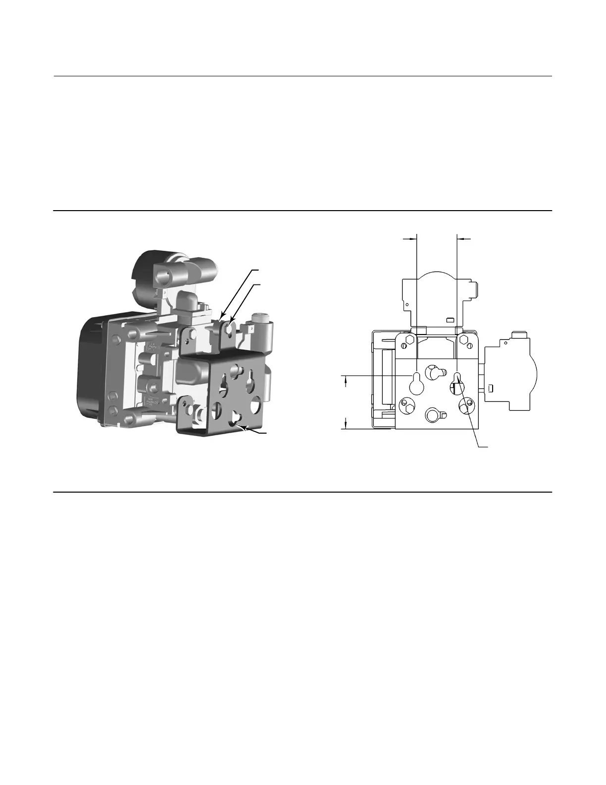
Wall Mounting
1. Install the wall mounting screws by using the mounting bracket as a template.
2. Install the mounting bracket to the back of the base unit using the spacers and screws provided in the mounting kit.
3. Slide the assembly on the wall mounting screws and tighten.
4. Proceed to Step 2—Connect the Pneumatic Tubing on page 19.
Figure 15. FIELDVUE DVC6205 Wall Mounting
1‐INCH 1/4‐20
HEX HEAD
SCREW
SPACER
MOUNTING
BRACKET
10C1796‐A
57
(2.25)
72
(2.82)
2 MOUNTING
HOLES
8.6/0.34
X0428
mm
(INCH)
 Loading...


