Quick Start Guide
D103556X012
DVC6200 Digital Valve Controllers
January 2017
12
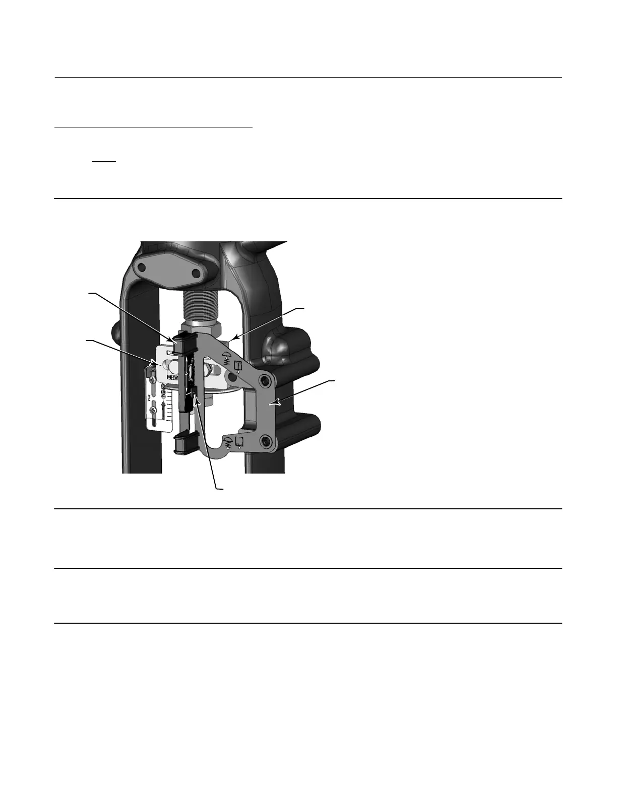
Air‐to‐Close (657 size 30i - 70i and GX)
Vertically align the magnet assembly so that the center line of the alignment template is lined up as close as possible
with the lower
extreme of the valid travel range on the magnet assembly. The magnet assembly should be positioned
so that the index mark on the pole pieces (back of the DVC6200 housing) is within the valid range on the magnet
assembly throughout the range of travel. See figure 9.
Figure 9. Air‐to‐Close Magnet Assembly Alignment
ALIGNMENT
TEMPLATE
INDEX MARK
FEEDBACK
PIECES
VALVE STEM
CONNECTOR
RETAINING
SLOT
1. Tighten the fasteners and remove the alignment template.
Note
Use a flat end hex key to tighten the magnet assembly fasteners to a torque of 2.37 N•m (21 lbf•in) for 4 mm screws, and
5.08 N•m (45 lbf•in) for 5 mm screws. For added security, especially in vibrating services, blue (medium) threadlocker may be
used on the fasteners.

 Loading...


