Quick Start Guide
D103556X012
DVC6200 Digital Valve Controllers
January 2017
19
Step 2—Connect the Pneumatic Tubing
NOTE:
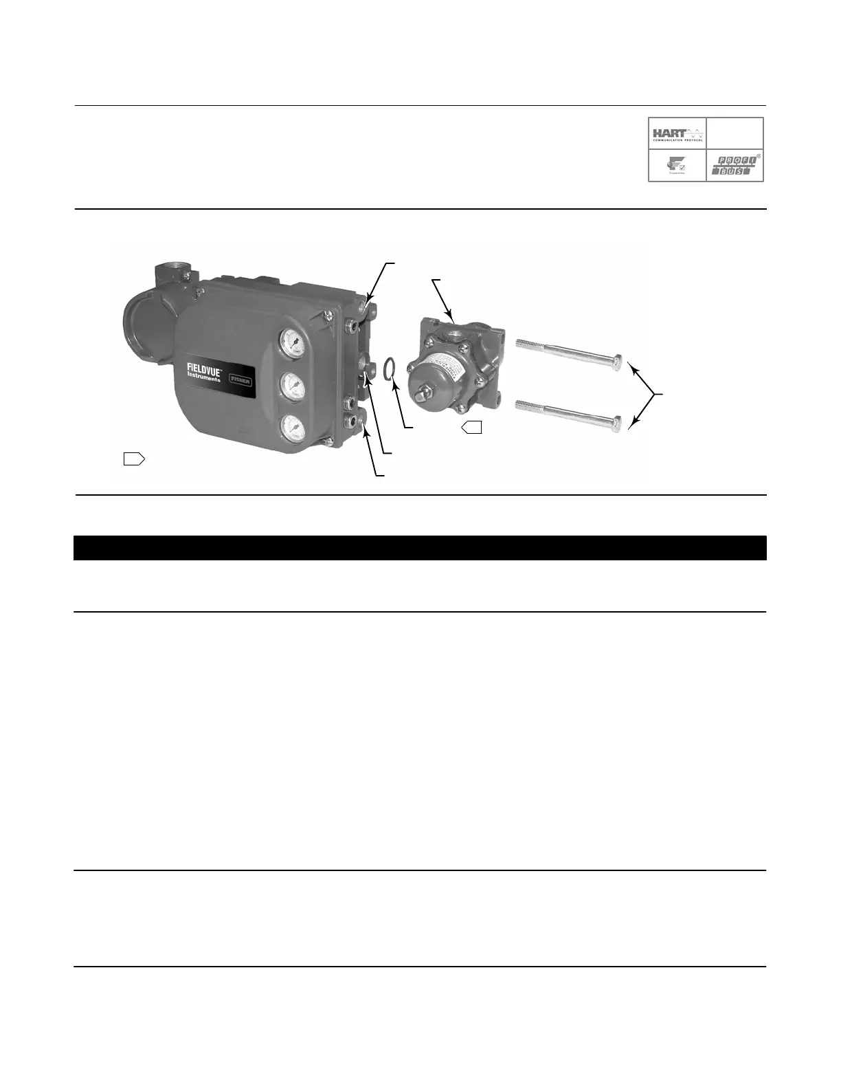
1 APPLY LUBRICANT
1
W9702-1
67CFR
CAP SCREWS
O‐RING
SUPPLY CONNECTION (1/4 NPT)
Figure 16. Integral Mounting of a Fisher 67CFR Regulator on a FIELDVUE DVC6200 Digital Valve Controller
OUTPUT A (1/4 NPT)
OUTPUT B (1/4 NPT)
CAUTION
Do not use sealing tape on pneumatic connections. This instrument contains small passages that may become obstructed
by detached sealing tape. Thread sealant paste should be used to seal and lubricate pneumatic threaded connections.
1. Connect the DVC6200 pneumatic output to the actuator input using at least 10 mm (3/8inch) diameter tubing.
D When using a singleacting direct digital valve controller (relay A or C) on a singleacting actuator, connect
OUTPUT A to the actuator pneumatic input.
D When using a singleacting reverse digital valve controller (relay B) on a singleacting actuator, connect OUTPUT
B to the actuator diaphragm casing.
D When using a doubleacting digital valve controller (relay A) on a doubleacting actuator, connect OUTPUT A and
OUTPUT B to the appropriate actuator pneumatic input. With no input current to the DVC6200, OUTPUT A is at
zero pressure and OUTPUT B is at full supply pressure when the relay is properly adjusted.
Note
To have the actuator stem extend from the cylinder with increasing input signal, connect OUTPUT A to the actuator cylinder
connection farthest from the actuator stem. Connect OUTPUT B to the cylinder connection closest to the actuator stem. To have
the actuator stem retract into the cylinder with increasing input signal, connect OUTPUT A to the actuator cylinder connection
closest to the actuator stem. Connect OUTPUT B to the cylinder connection farthest from the actuator stem.
SIS
 Loading...


