Quick Start Guide
D103556X012
DVC6200 Digital Valve Controllers
January 2017
38
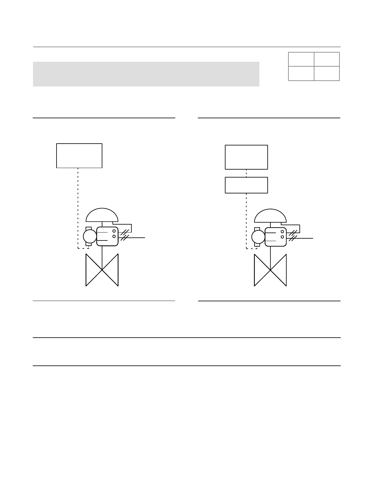
De-Energize to Trip (DETT) DVC6200 SIS,
no Solenoid Valve
In a typical deenergize to trip application without a solenoid valve, the logic solver trip signal deenergizes the digital
valve controller to 4 mA (or 0 VDC). This drives the digital valve controller to the no output pressure condition. As a
result, the safety valve moves to its noair, fail safe position.
Figure 30. FIELDVUE DVC6200 SIS Powered
with 4-20 mA
LOGIC SOLVER
AS
4-20 mA DETT
E1457
Figure 31. FIELDVUE DVC6200 SIS Powered
with 0-24 VDC
0-24 VDC DETT
LOGIC SOLVER
LC340
LINE CONDITIONER
AS
E1458
1. If the DVC6200 SIS is powered with 420 mA, connect the logic solver output card +/ terminals to the
corresponding DVC6200 SIS LOOP +/terminals.
Note
For the digital valve controller to operate with a 420 mA control signal the DIP switch must be in the pointtopoint loop position,
as shown in table 2. The control mode must be set to analog. This is set at the factory when ordered properly.
SIS
 Loading...


