Quick Start Guide
D103556X012
DVC6200 Digital Valve Controllers
January 2017
42
Energize to Trip (ETT) Digital Valve Controller and
De-Energize to Trip (DETT) Solenoid Valve
In this application, the logic solver trip signal deenergizes the solenoid valve, which opens the solenoid vent valve. The
digital valve controller is configured as energize to trip (ETT) and uses a reverse acting relay (Relay B) to drive the
digital valve controller to the no output pressure condition. The energize to trip option provides maximum actuator
pressure at minimum control signal (4 mA or low state). Therefore, loss of the control signal will not cause the safety
valve to trip. The safety valve moves to its noair, fail safe position when the logic solver (or DCS) sets the current to the
digital valve controller to 20 mA (high state). Partial stroke testing occurs at minimum control signal (4 mA or low
state).
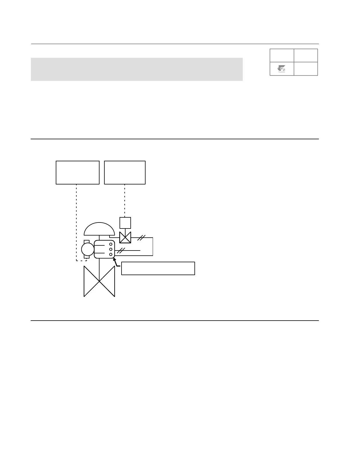
Figure 34. Digital Valve Controller and Solenoid Valve Powered Separately
LOGIC SOLVER
OR DCS
LOGIC SOLVER
ETT
0-24 VDC DETT
AS
S
SINGLE-ACTING, REVERSE (RELAY B)
4 mA = FULL SUPPLY TO ACTUATOR
E1459
1. Install the solenoid valve on the actuator casing or actuator yoke.
2. Install at least 10 mm (3/8inch) diameter tubing such that the solenoid valve is in the pneumatic path between the
digital valve controller output and the actuator input.
3. Connect the logic solver output card +/ terminals to the corresponding solenoid valve +/ wires.
4. Connect the logic solver (or DCS) output card +/ terminals to the corresponding digital valve controller LOOP +/
terminals.
5. Proceed to Step 4—Configure the Digital Valve Controller on page 33.
SIS
 Loading...


