Instruction Manual
D103175X012
GX Valve and Actuator
July 2017
18
16. Remove the Belleville spring pack (key 34) and packing spacer (key 30) from the bonnet (key 4). Carefully push out
the remaining packing box parts from the bonnet (key 4) using a rounded rod or other tool which will not scratch
the packing box wall. Clean the packing box and the metal packing box parts.
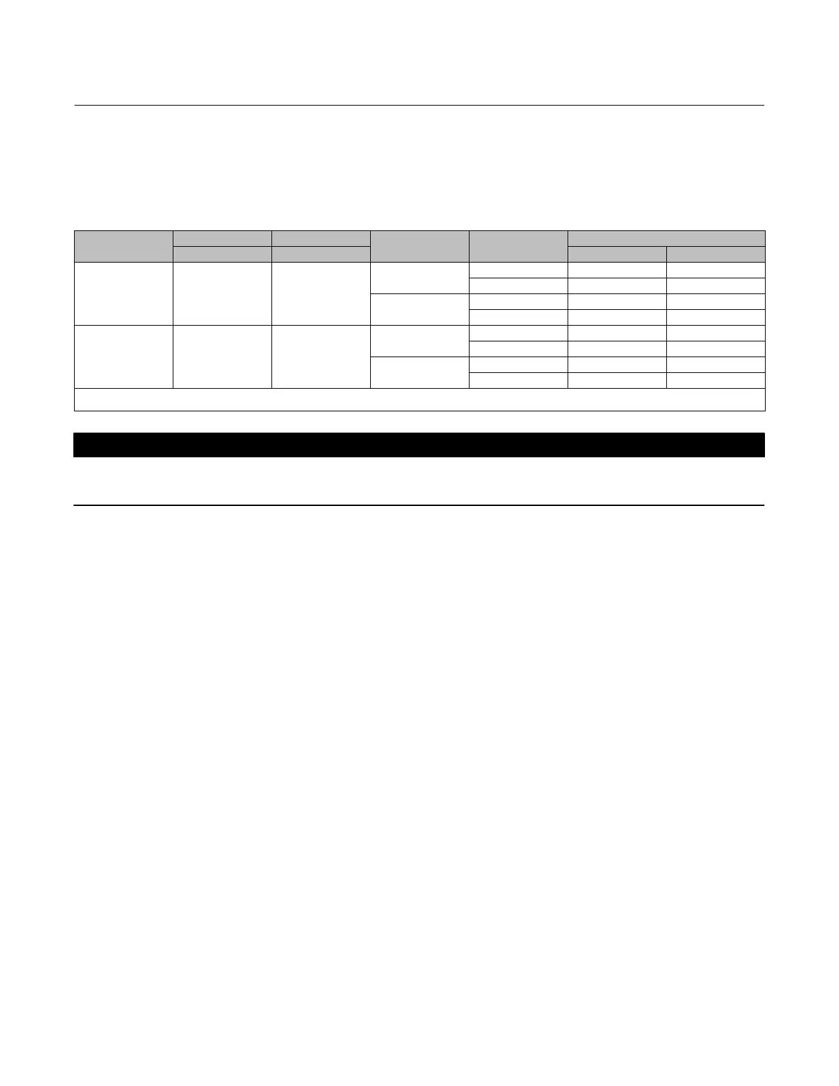
Table 11. GX Electric Actuator Maximum Allowable Thrust
VALVE SIZE
STEM DIAMETER TRAVEL
BONNET STYLE
STEM MATERIAL
STRENGTH
MAXIMUM THRUST
mm mm N lbf
DN25 to DN50
(NPS 1 to 2)
10 20
Plain
High
(1)
17000 3820
Low
(2)
7600 1710
Bellows/Extension
High
(1)
11400 2560
Low
(2)
6700 1500
DN80 to DN100
(NPS 3 to 4)
14 20, 40
Plain
High
(1)
20000 4500
Low
(2)
20000 4500
Bellows/Extension
High
(1)
20000 4500
Low
(2)
14500 3260
1. High strength stem materials consist of S200910, N05500, S31603.
2. Low strength materials consist of S31803, N10675, N06022.
CAUTION
Inspect the valve stem, threads and packing box surfaces for any sharp edges that might cut the packing. Scratches or burrs
could cause packing box leakage or damage the new packing.
17. Inspect the valve stem, threads and packing box surfaces for any sharp edges that might cut the packing.
Scratches or burrs could cause packing box leakage or damage the new packing. If the surface condition cannot be
improved by light sanding, replace the damaged parts.
18. Remove the covering protecting the valve cavity and install a new valve/yoke gasket (figures 18, 19, 20, and 21
key 5, figures 22 and 23 key 47) making sure that the gasket seating surfaces are clean and smooth.
19. Carefully install the bonnet (key 4) onto the valve stem.
20. Install the new packing and the metal packing box parts according to figure 15 for ENVIRO-SEAL PTFE packing and
according to figure 16 for ENVIRO-SEAL graphite ULF packing. Place a smooth‐edged pipe over the valve stem and
gently tap each soft packing part into the packing box. Apply anti‐seize lubricant to the threads and install the
packing follower (key 29).
21. Install the locknut (key 28) and stem adjustor nut (key 27). Ensure they are aligned with the mark made on the
stem disassembly and tighten
For standard bonnet constructions, install the valve plug/bonnet sub assembly into the valve body (key 1).
22. Mount the actuator onto the valve and install the body nuts (figures 18, 19, 20, 21 key 7, figures 22 and 23 key
46), but tighten them only finger‐tight.
23. For standard bonnet constructions, tighten the body nuts (key 7) evenly using a cross‐tightening procedure. See
table 4 for torque requirements.
For extension and bellows bonnet constructions, tighten the bonnet nuts (key 46) evenly using a cross‐tightening
procedure. See table 5 for torque requirements.
24. Push the valve plug/stem to the valve seat. Thread the stem adjustor nut (key 27) and locknut (key 28) to the
previously marked position. Thread the locknut (key 28) up against the stem locknut and tighten to the torque
specified in table 6.
25. Stroke the actuator rod until it contacts the stem adjuster nut (key 27) and install the stem connector halves and
travel indicator (keys 23, 24, and 26) with the cap screws (key 25). Install the stem connector halves in the proper
orientation so that when looking at the inside of the stem connector halves, the flats are down and the beveled
surfaces are up.