System must be protected from freezing
Firm level surface AFTER the pressure tank
3-prong, 120V outlet within 5 ft. (1.5 m) of the control head with constant
power. GFCI outlet is recommended. Use of an extension cords is not
A 1.5 inch standpipe, sump pit, or outside drain.
PP l l ee aa s s ee nn oo t t ee : :
line is pressurized and can be ran vertically if necessary.
VV EE RR I I FF YY SS YY SS TT EE MM II NN VV E E NN T T OO RR YY
Use the following table to help verify the parts that are included with your system and verify that they
are all accounted for. Inspect all parts for damage and report any damage immediately. Damage claims
must be made within 30 days of delivery to be eligible for replacement.
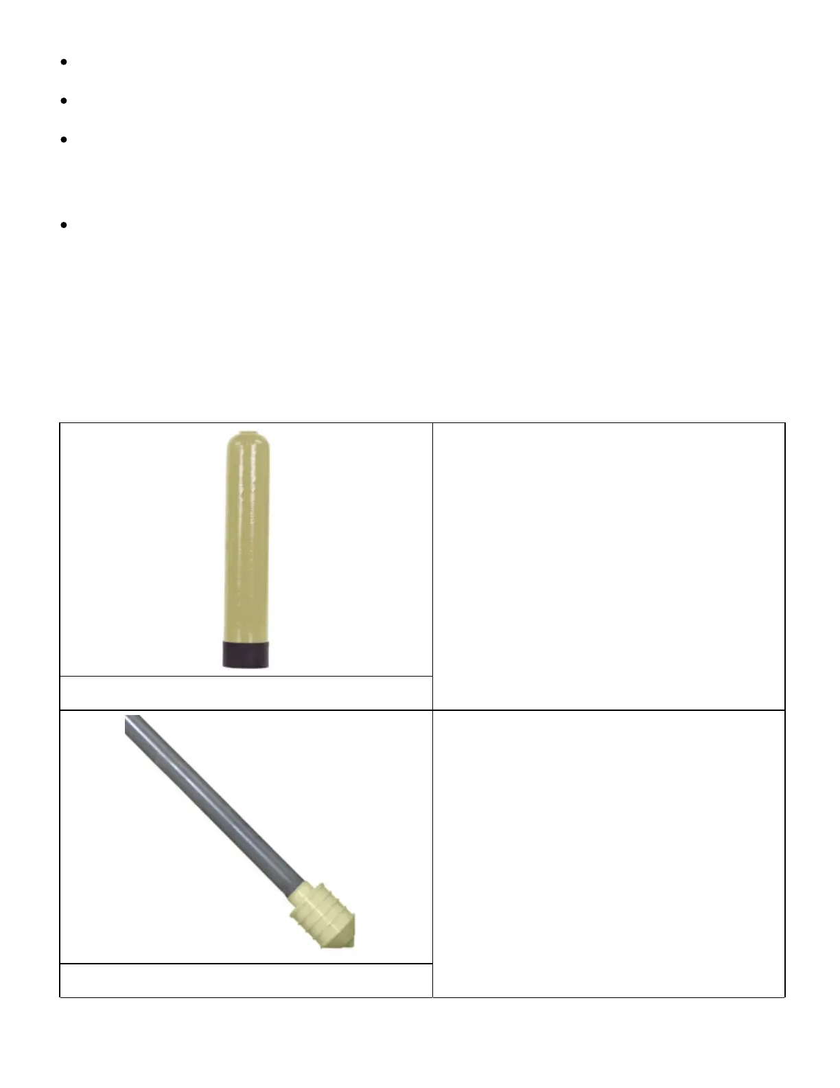
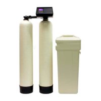
A tall slender tank 44–65 inches in height with
an opening on the top. Tanks that are 14 inches
or larger may have a gray threaded adapter to
reduce tank opening to match control head.
PP oo l l y y gg l l aa s s s s TT aa nn kk
A tall pipe that runs from the bottom of the
tank to the control valve. One end has a basket
(basket design varies) and it usually ships inside
RR i i s s ee r r / / DD i i s s t t r r i i bb uu t t oo r r TT uu bb ee
2 of 19