EasyManua.ls Logo

Fleck 7000SXT User Manual

Fleck 7000SXT
42 pages
To Next Page IconTo Next Page
Page #1 background imageLoading...
Page #1 background image
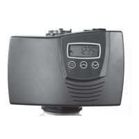
Model 7000SXT
Service Manual
IMPORTANT: Fill in Pertinent Information on Page 3 for Future Reference

Questions and Answers:

Fleck 7000SXT Specifications

General IconGeneral
DisplayLCD
Inlet/Outlet1" NPT
Operating Pressure20 - 125 psi
Maximum Pressure125 psi
Bypass ValveOptional
MountingTop mount
Warranty5 years limited
ProgrammingUser-programmable
Regeneration TypeMetered or Timed
Valve Size1 inch
Brine Line Connection3/8 inch
Riser Tube Diameter1.05"
Operating Temperature34 - 120°F (1 - 49°C)
Mounting Base2 1/2" - 8 NPSM

Summary

Job Specification Sheet

Installation Instructions

Start-Up Instructions

Timer Features

Setting the Time of Day

Procedure to set the current time of day on the control unit's display.

Queueing a Regeneration

How to schedule a regeneration cycle to occur at a later time.

Regenerating Immediately

Method to initiate a regeneration cycle on demand.

Timer Operation

Meter Immediate Control

Regenerates based on water usage as soon as system capacity is depleted.

Meter Delayed Control

Regenerates at a programmed time after system capacity is depleted.

Time Clock Delayed Control

Regenerates on a timed interval at a programmed regeneration time.

Day of the Week Control

Regenerates on a weekly schedule based on user-defined days.

Control Operation During Regeneration

Explains display information and user interaction during a regeneration cycle.

Control Operation During Programming

Details how the control operates while in programming mode.

Manually Initiating a Regeneration

Step-by-step guide to manually start a regeneration cycle.

Control Operation During A Power Failure

Describes the unit's behavior and memory retention during power outages.

Master Programming Mode Chart

Master Programming Mode

Setting the Time of Day

Procedure to set the current time of day within the programming mode.

Entering Master Programming Mode

Steps to access the master programming interface.

Exiting Master Programming Mode

Procedure to save settings and return to normal operation.

Resets

Instructions for performing soft and master resets of the unit.

Display Format

Setting the unit of measure and time display format.

Valve Type

Specifies the type of regeneration cycle the valve follows.

Control Type

Determines how the control triggers a regeneration cycle.

Number of Tanks

Configuration for single or dual tank water softener systems.

Tank in Service

Selection of which tank is active in a two-tank system.

Unit Capacity

Sets the treatment capacity of the system media in grains.

Feedwater Hardness

Input for the hardness level of the incoming water supply.

Reserve Selection

Choice between percentage safety factor or fixed reserve capacity.

Safety Factor

Sets the percentage of system capacity reserved for regeneration.

Fixed Reserve Capacity

Sets a fixed volume reserve capacity for the system.

Day Override

Sets the maximum number of days between regeneration cycles.

Regeneration Time

Specifies the time of day for regeneration initiation.

Regeneration Cycle Step Times

Adjusts the duration for each step of the regeneration cycle.

Day of Week Settings

Schedules regeneration for specific days of the week.

Current Day

Sets the current day of the week for day-of-week controls.

Flow Meter Type

Identifies the type of flow meter connected to the control.

Meter Pulse Setting

Configures the meter constant for non-standard flow meters.

User Programming Mode

User Programming Mode Steps

Guide to setting day override, regeneration time, and feedwater hardness.

Diagnostic Programming Mode

Diagnostic Programming Mode Steps

Steps to view flow rate, peak flow, hours in service, volume used, and software version.

Powerhead Assembly

Valve Assembly

Valve Assembly Parts List

Detailed list of parts for the valve assembly, including DLFC options.

Bypass Assembly

2310 Safety Brine Valve

Troubleshooting

Error Codes

Explanation of error codes and their corresponding reset and recovery procedures.

Removing Gear Box Assembly

Inserting Circuit Board

Connecting the Circuit Board

Water Conditioner Flow Diagrams

In Service Position

Diagram showing water flow path when the unit is in normal service.

Backwash Position

Diagram illustrating water flow during the backwash regeneration cycle.

Brine Position

Diagram showing water flow path during the brine draw cycle.

Slow Rinse Position

Diagram illustrating water flow during the slow rinse regeneration cycle.

Rapid Rinse Position

Diagram showing water flow path during the rapid rinse regeneration cycle.

Brine Tank Refill Position

Diagram illustrating water flow during the brine tank refill process.

Injector Flow Data

Meter Flow Data

Dimensions

Notes