41
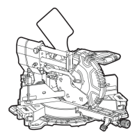
SMS 305 18-EC
WARNING!
Always turn the saw off and remove the
battery before making any adjustments or
assembling parts.
WARNING!
Always wear gloves when changing or
handling blades. Blade tips are sharp and
can cause personal injury.
WARNING!
Only use wood-cutting blades that have a
saw- blade diameter in accordance with the
markings on the saw and are marked with a
speed equal or higher than the speed marked
on the tool.
To remove the blade
Raise the saw arm by releasing the arm-
lock pin (5) and position the saw at 0°
bevel.
Tighten the slide-rail lock knob (4) so that
the saw head is secured in forward place.
Push the spindle lock (21) down.
Lift and hold the lower blade guard (19).
Rotate the blade slowly until it fully seats
into its locked position.
Loosen the blade bolt (H-1) clockwise with
the supplied double-ended Allen wrench
(38).
Remove the blade bolt (H-1), the outer
flange (H-2), and the blade (H-3). Do not
remove the inner flange (H-4). Wipe the
flanges and shaft to remove dust and
debris. Inspect the parts for damage.
Replace if needed.
To install the blade
Ensure that the inner flange (H-4) is
properly installed in the spindle.
Match the arrow direction on the blade
with the arrow direction on the lower blade
guard (19). Make sure that the teeth of the
blade are pointing downward.
Fit the saw blade onto the inner flange
support ring (H-5).
Install the outer flange (H-2).
Push the spindle lock (21) down and use
the Allen wrench (38) to turn the blade
bolt (H-1) counterclockwise until the lock
engages. Securely tighten the blade bolt.
Be sure the spindle lock (21) is released so
the blade turns freely.
WARNING!
After installing a new blade, make sure
the blade does not interfere with the kerf
insert (17) at 0° and 45° bevel positions
..
Lower the blade into the blade slot and
check for any contact with the base or table
structure. If the blade contacts base or table,
seek authorized service.
Adjustments
WARNING!
Always turn the tool off and remove the
battery pack before making any adjustments
or assembling parts.
NOTE
The miter saw was completely adjusted at
the factory. However, during shipment, slight
misalignment may have occurred. Check the
following settings and make adjustments, if
necessary, prior to using the miter saw.
Aligning the scale for miter
angles (see figure I1-I2)
WARNING!
Risk of injury if the table is not latched.
Always tighten the miter locking knob (16)
before you perform a cut.
Position the saw head to the closest
position in relation to the fence. And use
the arm-lock pin (5) to secure the saw head
in place.
Set the miter table at 0°, and set bevel
angle of saw head at 0°.
Checking:
Position 90° corner of a combination
square between the sliding fence (6) and
the saw blade on the miter table.
The side of the combination square must be
flush with the saw blade over the complete
length.
Adjusting (if necessary):
Loosen all four screws (I-2) with the
supplied double-ended Allen wrench (38)
and turn the miter table together with
the miter scale (11) until the side of the
square is flush with the saw blade over the
complete length.