44
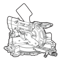
SMS 305 18-EC
The table can be latched at these miter-
detent slots (L-1).
Detent position
Left Middle Right
45°; 31.6°;
22.5°; 15°
0°
15°; 22.5°; 31.6°;
45°; 60°
Adjusting bevel angle (see figure
M)
WARNING!
After each adjustment of the angle for a bevel
cut, always check that the saw blade has
clearance.
Unlock the bevel lock lever (14) by lifting it
up to the Bevel Unlocked Position (M-2)
or until you feel that the saw head can be
tilted.
Tilt the saw until the bevel-angle indicator
(29) points to the desired angle on the
bevel scale plate (28).
Lock the bevel lock lever (14) by pressing
it down to the Bevel Locked Position
(M-3).
For quick, accurate selection of the
commonly used inclination angles, the
saw head can be latched at any of several
positions. Tilt the saw head until the bevel-
detent pin completely snapped into
the bevel-detent slot. A click sound that
indicates the override function is engaged.
To disengage, lift the bevel lock lever (14)
to the Bevel Override Position (M-1).
Detent positions
Left Middle Right
45°; 33.9°; 22.5° 0° 22.5°; 33.9°; 45°
Unlocking/locking the saw arm
(see figure N)
To unlock and raise the saw arm (Working
Position):
Firmly grasp the main handle (1) and apply
downward pressure while at the same time
pulling the arm-lock pin (5) out so that it
stops in unlock position.
Slowly raise the saw arm.
To lock the saw arm (Transport Position):
Firmly grasp the main handle (1) and apply
downward pressure until head stops.
Push in the arm-lock pin (5) toward the
saw, allowing it to lock the saw into place.
Slide-rail lock knob (see figure O)
Loosen the slide-rail lock knob (4) to
slide the saw head through the sliding
mechanism forward or backward to the
desired position.
Be sure to tighten the slide-rail lock knob
(4) after the desired position is reached.
Setting cutting depth (see figure
P)
The depth stop is a feature provided to allow
for (normal) full-depth cuts or non-through
cuts used to cut grooves.
Remove the battery.
Make sure the arm-lock pin (5) is
disengaged.
Press the depth stop plate (22) down.
Grip the main handle (1) and push the saw
head down while watching the depth stop
bolt (23) contact the surface of the depth
stop plate (22).
Rotate the bolt (23) and watch the bottom
of the saw blade move. This adjustment
sets the depth of cut.
When making normal, full-depth cuts, push
the depth stop plate (22) up and the bolt
(23) pass through the depth stop plate (22)
without any binding or contact with the
plate.
Sli
ding fences (s
ee figure Q)
Loosen the sliding fence lock knob
(24) at each side by rotating the knob
counterclockwise, then slide the fences (6) in
or out to install or remove them.
When the desired position of the sliding
fences (6) is reached, tighten the lock knob
(24) by rotating the knob clockwise.
WARNING!
Before operating the tool, make sure that
the sliding fences (6) are secured firmly.
Long workpiece support (see
figure R1-R2)
WARNING!
Long workpieces have a tendency to tip
over unless clamped down and properly
supported from underneath.