43
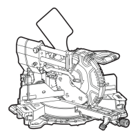
SMS 305 18-EC
Setting the standard bevel angle
45° (see figure K1-K7)
Position the saw head to the closest
position in relation to the fence. And use
the arm-lock pin (5) to secure the saw head
in place.
Move the sliding fence (6) all the way out
along the horizontal direction.
Set the miter table at 0°, and set bevel
angle of saw head at 45°.
Checking:
Place 45° corner of combination square
between the saw blade and miter table.
Adjusting the miter angle (see
figure L1-L2)
The miter locking knob (16) and miter detent
release lever (15) allow you to miter your saw
to 60° right and 52° left.
Loosen the miter locking knob (16) by
turning it counterclockwise.
Pull the miter detent release lever (15)
up, and hold it in this position or push
the buckle (L-2) forward to lock the miter
detent release lever (15) .
Rotate the miter arm to the left or right and
set the desired miter angle by using miter-
angle indicator (13).
Release the miter detent release lever (15)
and tighten the miter locking knob (16) by
turning it clockwise.
For quick, accurate selection of the
commonly used miter angles, there are
miter-detent slots (L-1) on the miter-angle
scale. Loosen the miter locking knob (16)
and move the miter arm until the miter-
detent pin (L-3) completely snaps into the
miter-detent slot (L-1). A click sound that
indicates the override function is engaged.
To disengage, pull the miter detent release
lever (15) upward.
Saw blade position Adjustment
Rightward
The angle between the
saw blade and table is
greater than 45° (see
figure K3)
Loosen the set screw A counterclockwise.
Gently push the saw head toward right.
Use the combination square to check the bevel 45°
again.
The angle between the
saw blade and table
is less than 45° (see
figure K4)
Tighten the set screw A clockwise.
Watch the saw blade tilt and use the combination
square check the bevel 45°.
Leftward
The angle between the
saw blade and table
is less than 45° (see
figure K5)
Tighten the set screw D clockwise.
Watch the saw blade tilt and use the combination
square check the bevel 45°.
The angle between the
saw blade and table is
greater than 45° (see
figure K6)
Loosen the set screw D counterclockwise.
Gently push the saw head toward left.
Watch the saw blade tilt and use the combination
square check the bevel 45°.
Adjusting(if necessary):
Unlock the bevel lock lever (14).
Tilt the saw assembly to the left or right to
45°.
Open the cover (J-3), according to the
table below, adjust the set screw A and D.
Use the double-ended Allen wrench (38) to
adjust the set screw A or D (the set screw A
is for adjusting right bevel 45° and the set
screw D is for adjusting left bevel 45°).
After the adjustment is finished, reinstall
the cover (J-3).