42
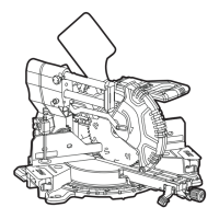
SMS 305 18-EC
Retighten the screws (I-2) again.
When the miter-angle indicator (13) is not in
line with the 0° mark of the miter scale (11)
after adjusting, loosen the screw (I-1) with
double-ended Allen wrench (38) and align
the angle indicator (13) alongside the 0°
mark.
S
etting the standard bevel angle
0° (see figure J1-J7)
Position the saw head to the closest
position in relation to the fence. And use
the arm-lock pin (5) to secure the saw head
in place.
Set the miter table at 0°, and set bevel
angle of saw head at 0°.
Checking:
Position 90°corner of a combination
square between the miter table and the
saw blade.
The side of the square must be flush with
the saw blade over the complete length.
Adjusting (if necessary):
Unlock the bevel lock lever (14).
Bring the miter saw onto the workbench
and the rear of the saw slightly exceeds
the work surface of the workbench shown
in figure J2.
Tilt the saw head to the left and right until
it hits the 0° stop in the vertical position
– this is where the saw is currently set to
make a 0° cut.
Remove the back cover (J-1) by using the
double-ended Allen wrench (38) to loosen
the six screws shown in figure J3.
Loosen the two bolts (J-2)
counterclockwise at least one turn by using
an open end wrench or socket wrench (not
supplied) shown in figure J4.
Open the cover (J-3), according to the
table below, adjust the set screw B and C.
After the adjustment is finished, use the
combination square to check the bevel 0°
again.
Retighten the two bolts (J-2), reinstall the
back cover (J-1) with six screws, and then
reinstall the cover (J-3).
In case of the bevel-angle indicator (29) is
not in line with the 0° mark of the bevel scale
after the adjustment, loosen the two screws
(J-4) by using double-ended Allen wrench (38)
and align the angle indicator (29) with the 0°
mark shown in figure J7.
Saw blade position Adjustment
Saw blade deflects to the
right (see figure J5)
Loosen the set screw C counterclockwise (1.) about 2-3 turns by
using the double-ended Allen wrench (38).
Tighten the set screw B (2.) until the blade is fully aligned with
the combination square’s body’s edge.
Tighten the set screw C.
Saw blade deflects to the
left (see figure J6)
Loosen the set screw B counterclockwise about 2-3 turns by
using the double-ended Allen wrench (38).
Tighten the set screw C (2.).
Gently push the saw head to the right to hit the 0° stop until
the blade is fully aligned with the combination square’s body’s
edge.
Tighten the set screw B.