8 Installation of the transducers FLUXUS F808, F809
UMFLUXUS_F808_8091V1-2-1EN, 2019-08-23 77
8 Installation of the transducers
8.1 Pipe preparation
• The pipe has to be stable. It has to be able to withstand the pressure exerted by the transducer mounting fixture.
Rust, paint or deposits on the pipe absorb the sound signal. A good acoustic contact between the pipe and the transduc-
ers is obtained as follows:
• Clean the pipe at the selected measuring point:
– If present, the paint layer has to be smoothed by sanding. The paint does not need to be removed completely.
– Remove any rust or loose paint.
• Use coupling foil or apply a bead of acoustic coupling compound along the center line of the contact surface of the trans-
ducers.
• Observe that there must be no air pockets between the transducer contact surface and the pipe wall.
8.2 Orientation of the transducers and transducer distance
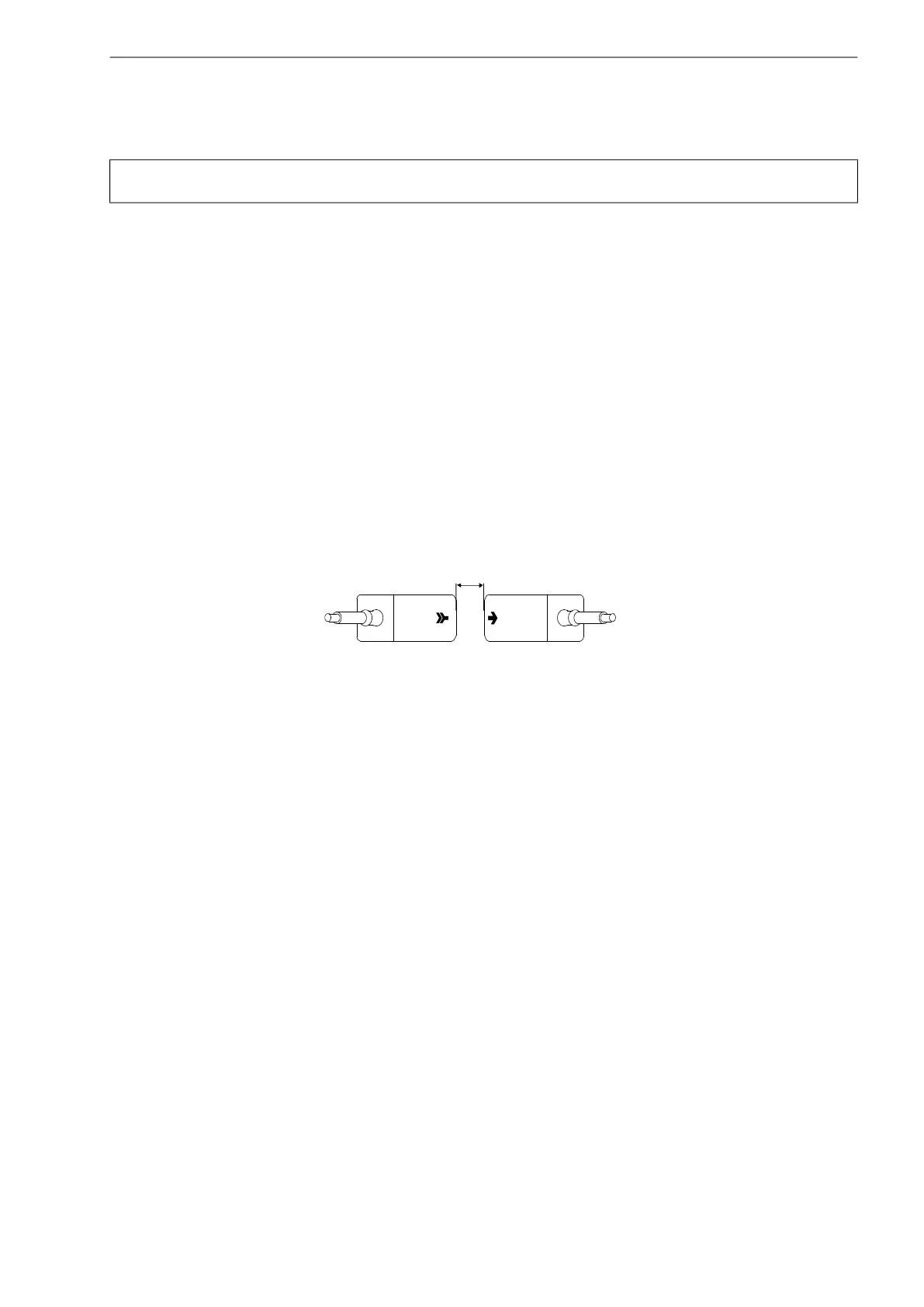
Mount the transducers onto the pipe in such way that the engravings on the transducers form an arrow (see Fig. 8.1). The
transducer cables show in opposite directions.
The transducer distance is the distance between the inner edges of the transducers (see section 3.3 and Fig. 8.1).
For the determination of the flow direction see section 10.8.
Select the installation instructions that correspond to the supplied transducer mounting fixture:
• Variofix L: see section 8.3
• Variofix C: see section 8.4
• PermaFix: see section 8.5
Attention! Observe the Safety Instructions for the Use in Explosive Atmosphere (see document SIFLUXUS,
SIFLUXUS_808_FM,SIFLUXUS_808_F2 and SIFLUXUS_1N62).
Fig. 8.1: Correct orientation of the transducers and transducer distance
transducer distance
 Loading...


