IRCamSafeEX-AXB/C Ex d enclosures for infrared cameras
8
The level of explosion protection afforded largely depends on compliance with
the IP protection class. When carrying out any work on or involving the enclo-
sure, ensure that all seals are positioned correctly and are in perfect condition.
8.8.1 Installing the connection lines
8.8.1.1 Lines
The quality of the supply pipe used must meet the thermal and mechanical requirements
in the area of application. The cables must comply with the applicable guidelines for di-
rect entry into flameproof enclosures in EN 60079-14. Cable glands must be sealed with
a sealing compound to waterproof the individual wires.
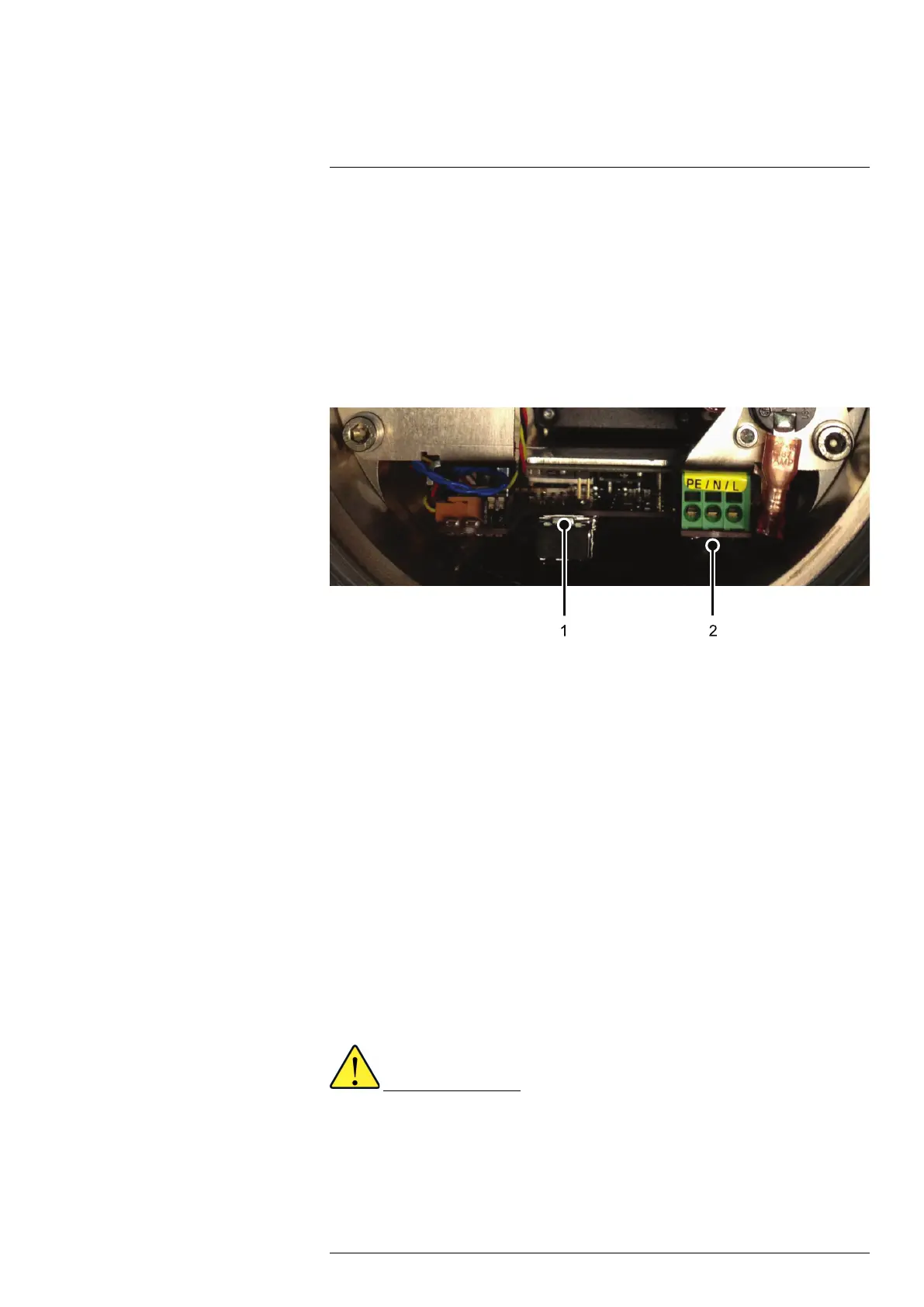
Figure 8.2 Connections on the controller board. 1, fiber-optic lucent; 2, supply line connection
8.8.1.2 Unscrewing the rear enclosure cover
1. Unscrew 1 × enclosure index screw.
2. Unscrew 4 × enclosure locking screws.
3. Position the assembly wrench on the rear cover and unfasten the enclosure cover.
4. Carefully remove the enclosure cover.
8.8.1.3 Installing the connection lines
1. Feed the connection lines with all external insulation through the cable glands into
the terminal compartment.
2. Ensure that the cable diameter matches the clamping cross-section on the cable
gland. Ensure that the cable gland is sealed using a sealing compound in line with
the instructions for cable glands.
3. Tighten the hexagonal nuts for the cable gland so that the terminal compartment is
sealed and the cable anchorage at the connection points is secure.
4. The tightening torque required can be found in the instructions for the components.
5. Install the connection lines in the terminal compartment so that:
• The permitted minimum bending radii values for each wire cross-section are
reached.
• Mechanical damage to the cable insulation is avoided.
Incorrect installation
• Please observe the thread sizes for the cable glands in the operating
instructions.
• The connection line must meet the applicable requirements, and the cross-
section dimensions must be sufficient. The diameter must comply with the ca-
ble gland requirements.
• Suitable lines must be selected and installed in such a way that the maximum
permitted wire temperatures are not exceeded.
#T559891; r.18204/18204; en-US
15



 To Next Page