Pin configurations and
schematics
13
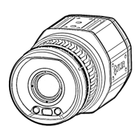
13.1 Pin configuration for camera I/O
connector
Pin Function Data
1 IN 1 opto-isolated, 0–1.5 V = low, 3–25 V = high
2 IN 2 opto-isolated, 0–1.5 V = low, 3–25 V = high
3
OUT 1 opto-isolated, ON = supply (max. 100 mA), OFF = open
4
OUT 2 opto-isolated, ON = supply (max. 100 mA), OFF = open
5
Supply VCC 6–24 VDC, max. 200 mA
6
Supply Gnd Gnd
Note Cables for digital I/O ports should be 100 m (328′) maximum.
13.2 LED indicators
The LEDs indicate the following:
Type of signal Explanation
The LED glows continuously orange. The camera is starting up.
The LED glows continuously red.
An error has been detected. Contact service.
The LED glows continuously green. The camera has started.
The LED flashes 10 times per second. An error has been detected. Contact service.
#T559950; r. AE/83475/83477; en-US
20
 Loading...