58,8mm
±1
2,31in
±0,04
72,5mm
±1
2,85in
±0.03
67mm
±0,1
2,64in
±0,004
216mm
±1
8,5in
±0,04
1in
±0,20
25mm
±5
73mm
±0,1
2,87in
±0,004
74,5mm
±0,1
2,93in
±0,004
40,8mm
1,6in
33,8mm
1,33in
72,5mm
2,85in
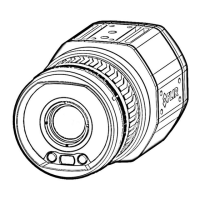
Camera with Lens IR f=24,6 mm (25°)
For additional dimensions see page 1
Sheet
Drawing No.
Size
Check
Drawn by
Denomination
A3
4(9)
T126925
Basic dimensions FLIR A/SC 6xx
AKZE
2022-01-14
R&D Thermography
Modified
1 2 3 4 5 6 7 8 9 10
A
B
C
D
E
F
G
H
1 32 54
C
F
B
D
G
E
A
6
Size
B
1:2
Scale
© 2012, FLIR Systems, Inc. All rights reserved worldwide. No part of this drawing may be reproduced, stored in a retrieval system, or transmitted in any form, or by any means, electronic, mechanical, photocopying, recording, or otherwise,
without written permission from FLIR Systems, Inc. Specifications subject to change without further notice. Dimensional data is based on nominal values. Products may be subject to regional market considerations. License procedures may apply.
Product may be subject to US Export Regulations. Please refer to exportquestions@flir.com with any questions. Diversion contrary to US law is prohibited.
 Loading...