910-0001-00-INS -R02 Page 13 of 53
Information contained in this document pertains to a Canadian origin product that is controlled as "dual use" by the Canadian
government. However, when in the United States or possessed by a US person, it may be considered a defense article from the US Government's
perspective. US government authorization may be required for re-transfer to a foreign person. If you have any questions, please contact FLIR's
Global Trade Compliance group at exportquestions@flir.com .
2 HARDWARE SYSTEM DESCRIPTION
2.1 HARDWARE COMPONENT DESCRIPTION
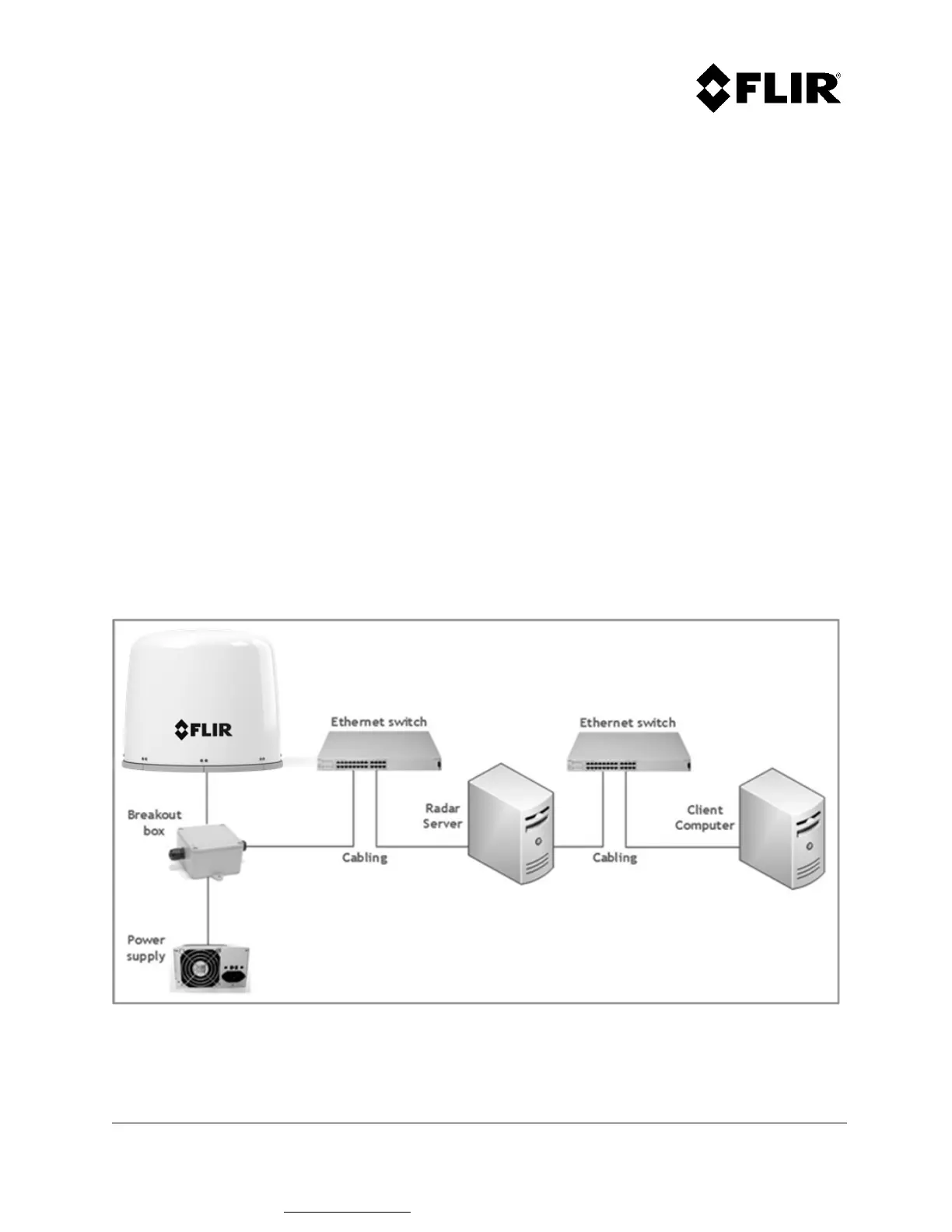
The R1, R2, R3, R3D, R5 and R5D Radar Systems comprise the following components. Some of these
components may not be needed, depending on the specific installation.
1. R1, R2, R3, R3D, R5 and R5D Radar Assembly
2. Radar Server computer
3. Client computer
4. Breakout box
5. Radar power supply
6. Network infrastructure
7. Cabling
2.2 PHYSICAL SYSTEM OVERVIEW
Figure 1 shows a typical hardware configuration of a R1, R2, R3, R3D, R5 and R5D Radar Systems.
Figure 1 - R1, R2, R3, R3D, R5 and R5D Radar Systems Physical Overview
 Loading...