910-0001-00-INS -R02 Page 35 of 53
Information contained in this document pertains to a Canadian origin product that is controlled as "dual use" by the Canadian government. However, when in
the United States or possessed by a US person, it may be considered a defense article from the US Government's perspective. US government authorization
may be required for re-transfer to a foreign person. If you have any questions, please contact FLIR's Global Trade Compliance group at
exportquestions@flir.com .
4.2.6 Antenna Tilt Adjustment Procedure — R5 and R5D
Step 1 The R5 and R5D tilt angle can be adjusted using the three screws on each side of the antenna
assembly. The central screw on each side is the adjustment screw that allows you to change the tilt
angle in increments of 1 degree. The two slot screws on each side of the adjustment screw allow you
to loosen the antenna assembly in order to change the tilt
angle. Remove the radome by first
unscrewing the 8 screws under the base of the unit
Step 2 Loosen the two slot screws on each side of the antenna
Step 3 Unscrew the alignment screw on each side of the antenna
Step 4 Position the alignment screw on each side of the antenna to the desired tilt angle
Step 5 Screw back the alignment screw on each side of the antenna
Step 6 Tighten the two slot screws on each side of the antenna
Step 7 Replace the radome and re-insert the 8 screws under the base of the unit, being careful not to
over-
tighten. Hand-tighten only until resistance increases - base seal should be compressed by
approximately 2mm
4.3 RADAR POWER DISTRIBUTION NETWORK INSTALLATION
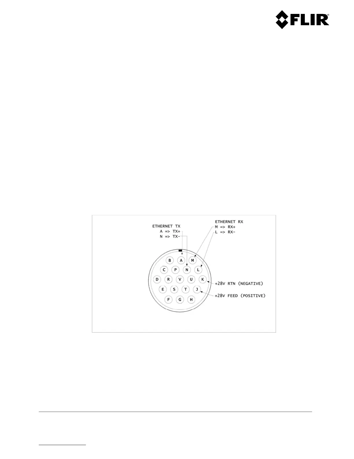
Electrical power is delivered to the radar through the power/data connector. A single weatherproof connector
is used to provide all external connections to the radar assembly. The connector is a “bayonet”- type
connector. The pin assignments are indicated in the figure and table below:
Figure 22 - Power/Data Connector Pin Out
 Loading...