Camera overview
6
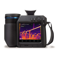
6.3 View from the bottom
1. Laser button.
2. Programmable button.
3. Tripod mount.
4. Cover for the connector compartment.
5. Battery.
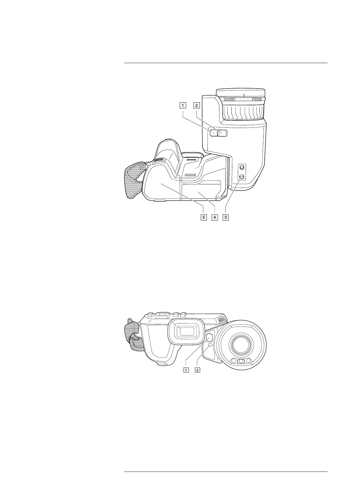
6.4 Laser distance meter and laser pointer
The laser distance meter consists of a laser transmitter and a laser receiver. The laser
transmitter also works as a laser pointer.
6.4.1 Laser transmitter and receiver
1. Laser receiver.
2. Laser transmitter.
6.4.2 Difference in position
This figure shows the difference in position between the laser transmitter and the optical
center of the infrared lens. The laser transmitter and the optical axis are parallel.
#T810413; r. AF/83467/83910; en-US
13
 Loading...