INSTALLATION, OPERATION, &
MAINTENANCE MANUAL
TITLE: F7000 / 8000 Series Rev. T
Pilot-Operated Safety Relief Valve Page 14 of 43
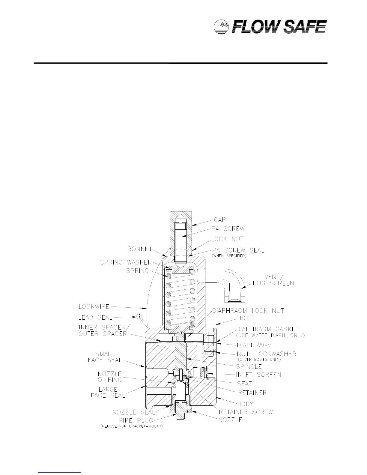
4) Carefully assemble the diaphragm to the top of the spindle by slowly turning the diaphragm clockwise
on the spindle threads until it bottoms on the shoulder. Make sure that there are no tears or rips in the
diaphragm material.
5) Apply small amount of Loctite 268 to diaphragm lock nut threads. Assemble inner/outer spacer(s) and
lock nut to the spindle. With a wrench on the nut, and a screwdriver in the top of the spindle, tighten
the parts together. Apply a small drop of Loctite to the nut threads. Make sure that the spacers are
centered to the extent possible.
6) Assemble the spring and spring washers atop the spindle.
7) Assemble the gasket (only if using a Teflon diaphragm) and then the bonnet over the spring and
spring washers onto the top of the diaphragm / body.
8) Apply Loctite 248 to 4 bonnet bolts and insert the bolts through the four holes in the body and bonnet
(washers and nuts also for older bodies).
9) Tighten the bolts to a torque of 5 - 6 ft.-lbs.
10) Insert the pressure adjustment screw into the top of the bonnet and install the lock nut.
11) Attach the pressure adjustment screw cap to the top of the pressure adjustment screw, but do not
tighten down.
12) Insert the inlet screen into the INLET port in the body.
13) Attach the vent / bug screen in the bonnet so that it faces away from the main valve mounting surface.
Face seals should then be positioned on the mounting face.
14) The pilot valve is now completely assembled and ready to be set per Section 5.0.
F100 PILOT VALVE ASSEMBLY
(Direct-Mount version shown)
 Loading...