INSTALLATION, OPERATION, &
MAINTENANCE MANUAL
TITLE: F7000 / 8000 Series Rev. T
Pilot-Operated Safety Relief Valve Page 5 of 43
2.1 DESCRIPTION / OPERATION
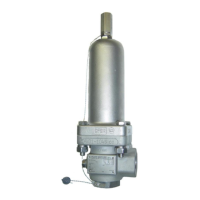
FLOW SAFE F7000 / 8000 Series pilot-operated relief valves have been furnished to industry with a
standard externally tubed pilot valve or, in nominal sizes up through 2 x 3 with an inlet rating of ANSI 900 or
above, with Integral Module (IM) construction. IM construction eliminates external tubing by relying on
porting within the main valve body for pressure actuation. Unless identified otherwise in this manual,
installation, startup, operation, and maintenance is the same for both styles of F7000 / 8000 Series valves.
Contact the factory for current availability of IM construction.
Referring to the figures on Page 4, system pressure is routed from below the valve through the pilot valve
to the “dome” cavity of the main valve. This dome pressure, acting on a piston area larger than the seat
area, creates a net positive downward force (F = P x A) which holds the main valve piston closed.
At the designated set pressure the pilot valve reduces dome pressure, allowing system pressure to lift the
main valve piston. With the modulating-style Model F100, F300, or F500 pilot, dome pressure is vented
proportionally to demand at set pressure. With the snap-acting Model F200 pilot, dome pressure is
completely vented at set pressure. Once system pressure is relieved, the pilot valve closes the main valve
at set pressure for the F100, F300, or F500, or at the preset blowdown pressure for the F200. Once the
dome is again pressurized up to system pressure, the main valve piston will be held in its closed position.
The F200 snap-acting pilot valve blowdown is adjustable from 3% to 20% of set pressure, and is normally
factory-set at 7 to 10% unless otherwise specified. The F100, F300, and F500 modulating pilot valves
provide zero blowdown; i.e., the main valve opens in proportion to demand and closes at the set pressure.
Set pressure for a valve with a pilot auxiliary setter is the pilot nameplate set pressure plus the auxiliary
setter nameplate differential pressure. Auxiliary setters are designated for use with specific valves by
means of matching serial numbers. If a valve has more than one auxiliary setter, different interface
diameters prevent them from being installed in the wrong order.
The F7000 / 8000 uses either an elastomeric or plastic seat on the piston to achieve bubble-tight seating.
A dynamic piston seal prevents any leakage from the dome to the discharge. Guide rings on the piston
eliminate metal-to-metal contact with the liner and help to provide smooth and consistent operation.
Elastomeric and plastic seals seal the main valve and pilot valves.
The orifice size may be easily selected by choosing a full-bore inlet nozzle (F7000 Series), or by converting
to a reduced-size orifice (F8000 Series) through the attachment of FLOW SAFE's unique annular-flow plug
to the bottom of the piston assembly. This plug reduces the effective flow area of the valve by directing the
fluid between the plug O.D. and the nozzle I.D.
2.2 SERVICE ENVELOPE
(1) Confirm low-temperature environmental applications with factory.
(2) Pilot valve MAWP’s: 740 psig (F100); 6000 psig (F200, F300, & F500)
SET PRESSURE, psig (barg)
-30 (-34) 275 (135) 15 (1) 6000 (413)
-30 (-34) 400 (204) 15 (1) 6000 (413)
-65 (-54) 225 (107) 15 (1) 6000 (413)
-65 (-54) 325 (163) 15 (1) 6000 (413)
-423 (-252) 400 (204) 15 (1) 1000 (69)
PEEK
-423 (-252)
0 (-18)
400 (204)
525 (273)
1000 (69)
3000 (307)
3000 (207)
6000 (413)
-423 (-252) 500 (260) 3000 (207) 6000 (413)