INSTALLATION, OPERATION, &
MAINTENANCE MANUAL
TITLE: F7000 / 8000 Series Rev. T
Pilot-Operated Safety Relief Valve Page 34 of 43
6.0 SUPPLEMENTAL TESTING AND ACCESSORIES
6.1 TESTING OF THE MAIN VALVE SUBASSEMBLY
When main valve reassembly is complete, the assembly should be tested for leakage and piston lift on a
test stand according to the following:
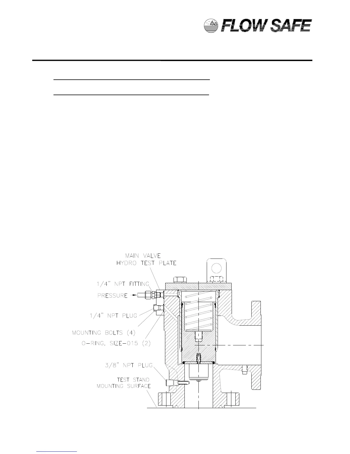
1) To enable separate control of pressure sources to the main valve dome and inlet, a hydro test plate
(available from FLOW SAFE) should be installed on the pilot mounting pad, as shown in the figure
below.
2) To test the piston seal, liner seals, and (for ‘IM’ construction) top spool piece seals, pressurize the
dome with 10% to 90% of set pressure. With a bubble tester, wet paper towel, or plastic wrap
covering the outlet, verify that there is no leakage. Also verify no leakage around the cap and cap
bolts by spraying the area thoroughly with soapy water.
3) To test the main valve seat, re-pressurize the dome as in (2), and introduce pressure at the inlet up
to 40% of dome pressure. Check for leakage at the main valve outlet.
4) Apply pressure to the field test connection to test the integrity of the FTC seals and (for ‘IM’
construction) the lower spool seal.
5) With no pressure to the dome, pressurize the inlet up to 5 psig. The piston should open slightly,
allowing air to discharge through the outlet of the valve.
6) To check for full piston lift, install a blind flange on the valve outlet. Again pressurize the inlet up to
5 psig. The piston should fully lift and hit the bottom of the cap, as indicated by a clear sound of
metal-to-metal contact. When the outlet flange is removed, the piston will frequently fall to the
closed position.
7) If the valve fails, disassemble the valve and examine the soft goods for contamination or damage,
or consult the troubleshooting guide in Section 7.0 of this manual.
F7000 MAIN VALVE ASSEMBLY TEST SETUP