INSTALLATION, OPERATION, &
MAINTENANCE MANUAL
TITLE: F7000 / 8000 Series Rev. T
Pilot-Operated Safety Relief Valve Page 38 of 43
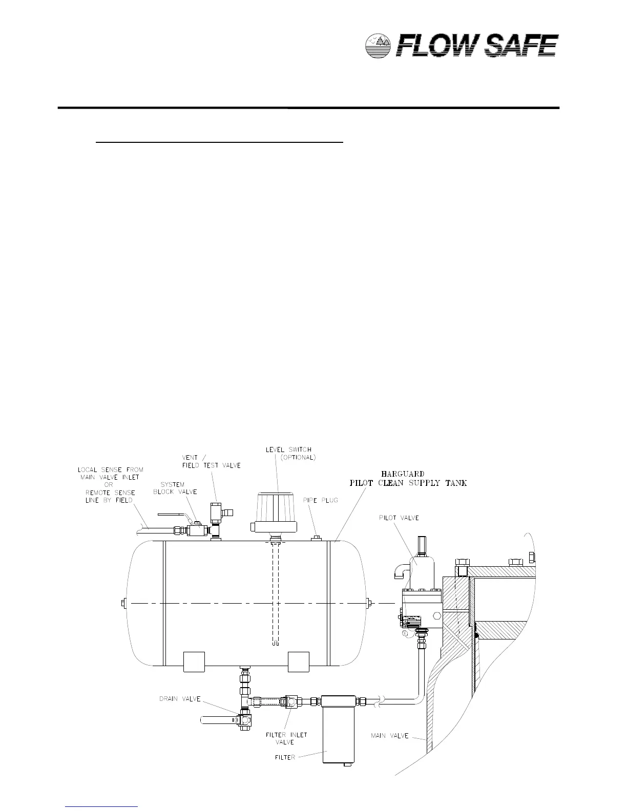
6.5 HARGUARD CLEAN PILOT SUPPLY TANK
The Harguard clean pilot supply tank isolates critical relief valve parts from a corrosive or dirty system
process, and permits only a clean liquid such as glycol and water to enter the pilot and main valve dome.
A relief cycle will cause the initial charge of clean liquid to be exhausted through the main valve outlet.
The subsequent repressurization through the tank will replenish clean liquid to the pilot and main valve
dome for a fixed number of relief cycles, depending on the valve size. The tank will then need to be
flushed and refilled for continued service.
1) For normal system operation, close the drain valve and vent / field test conn. valve, and open the
filter inlet valve and system block valve. Refer to illustration below.
2) When the liquid level is a minimum of 1/4 full, the tank will need to be flushed and refilled. With the
main valve inlet depressurized, close the system block valve and filter inlet valve, and open the vent /
field test valve. Remove the pipe plug from the spare connection on top of the tank. Open the drain
valve and flush the tank with a suitable liquid to remove sediment and other impurities.
3) To fill the tank, close the drain valve and open the filter inlet valve. The new liquid supply can be fed
in through the vent / field test valve or the open pipe plug connection. At this time, the filter drain plug
can be removed to provide a flush of the filter element.
4) Before pressurizing the relief valve, reinstall the filter drain plug and pipe plug at the top of the tank,
and close the vent / field test valve. Open the system block valve when ready to admit pressure to
the pilot and main valve dome. For remote-sensed systems, pressure should be restored to the main
valve inlet only after the pilot and dome are pressurized.