INSTALLATION, OPERATION, &
MAINTENANCE MANUAL
TITLE: F7000 / 8000 Series Rev. T
Pilot-Operated Safety Relief Valve Page 7 of 43
2.4 INSTALLATION
Prior to installation, check that the set pressure on the nameplate is as required, and meets the system
requirements. Lifting and handling should follow the instructions in Section 2.3.
If the valve has been in storage for a significant length of time, verify that the main piston can still freely
move by pushing on it manually through the valve inlet. If it does not return to the closed position, it may
be necessary to seat the piston using a pressure source connected to the field test, pilot, or main valve
cap.
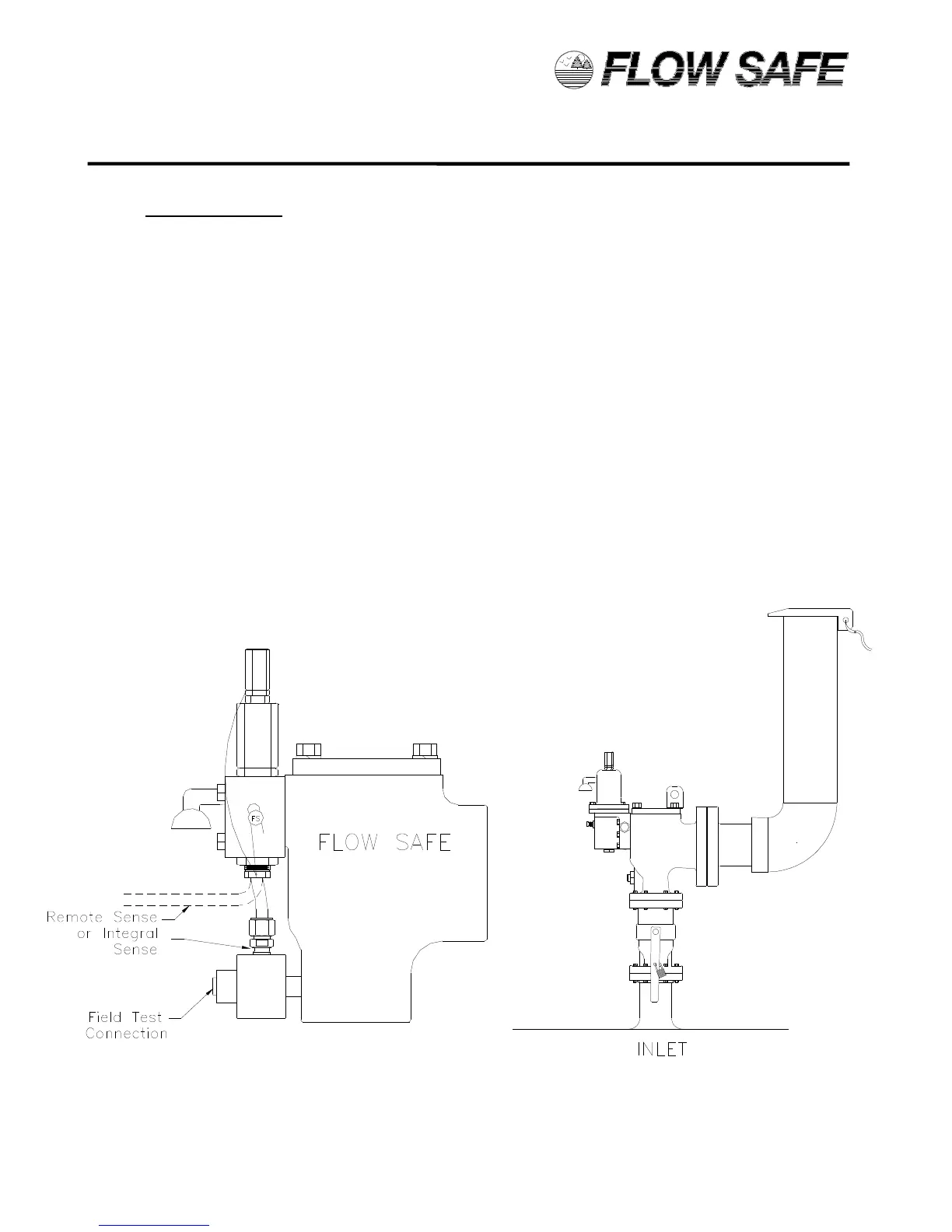
The F7000 or F8000 Series safety relief valve should be installed in the upright position per the figure
below, in accordance with accepted piping practices. Proper gaskets, lubricants and torques, as specified
in field procedures, must be used during assembly of bolted joints. Unless inlet pressure will be remotely
sensed (see Section 2.5), inlet piping pressure losses should not exceed 3% of the set pressure when the
valve is flowing [Ref. API 520 Part II]. Discharge piping should be configured so as to avoid accumulation
of ice and snow. Severe misalignments of inlet and outlet piping to the valves flanges should be avoided.
Adequate bracing of the inlet and outlet discharge piping must be provided to withstand the thrust force
created when the valve discharges.
If a block valve is used below the relief valve, it should be opened before pressurizing the system. This
block valve should be locked open during normal system operation.