11
6.3 Adjusting the valve
After every sleeve change, the closing of the valve has to be checked and adjusted. A
wrong adjustment may shorten the lifetime of the sleeve and cause leakage from the
valve when the actuator is in the closed position.
WARNING
Control the valve functions (see 2.3). Do not put tools or
parts of your body between the moving valve parts.
Before reinstallation of the valve into the pipeline:
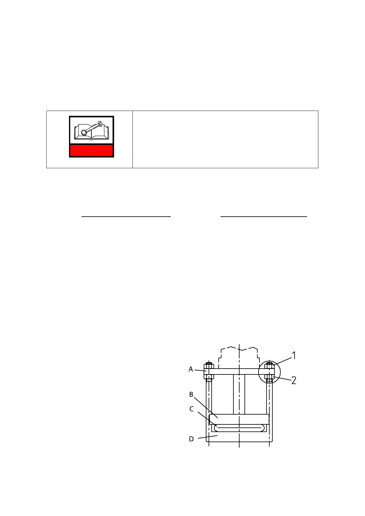
• Close the valve by using the actuator. Adjust the pinch bars parallel to each other
with the nuts, which are on both sides of actuator fixing plate (Fig.10, nuts 1 and 2),
so that from one end of the sleeve an even, narrow light strip (appr. 0.5 mm) is
shown on the whole squeezed point
of the sleeve or symmetrically on both sides (Fig.
10.1).
• Tighten both nuts (1) equally so, that the strip of light disappears.
• Unscrew the lower nuts (Fig. 10.2, nut 2) X mm from the attachment plate (see the
dimension X in the table, Fig. 11).
• When the nuts (Fig. 10.3, nut 1) on the upper side of the attachment plate are
tightened, the lower pinch bar rises and causes a sufficient squeeze on the sleeve to
close the flow against the pressure in the pipeline. After this has been done, open the
valve and it is ready to be installed to the pipeline.
If the valve is hand wheel operated, it is enough to check that the pinch bars are parallel
and the light slit is shown (Fig. 10.1). A sufficient squeeze is achieved by turning the
hand wheel 1/3...3/4 rounds after the valve feels tight: if the pressure in the pipeline is
1 bar - appr. 1/3 of a hand wheel rotation; PN 10 bar - appr. 1/2 of a hand wheel
rotation; PN 25 bar - appr. 3/4 of a hand wheel rotation. If the valve is supplied with a
reduction gear, the number of rotations is multiplied by the gear ratio.
A. Attachment plate
B. Upper pinch bar
C. Sleeve
D. Lower pinch bar
Fig. 10.