HDX USER INSTRUCTIONS ENGLISH 85392696 - 01/11
Page 19 of 60
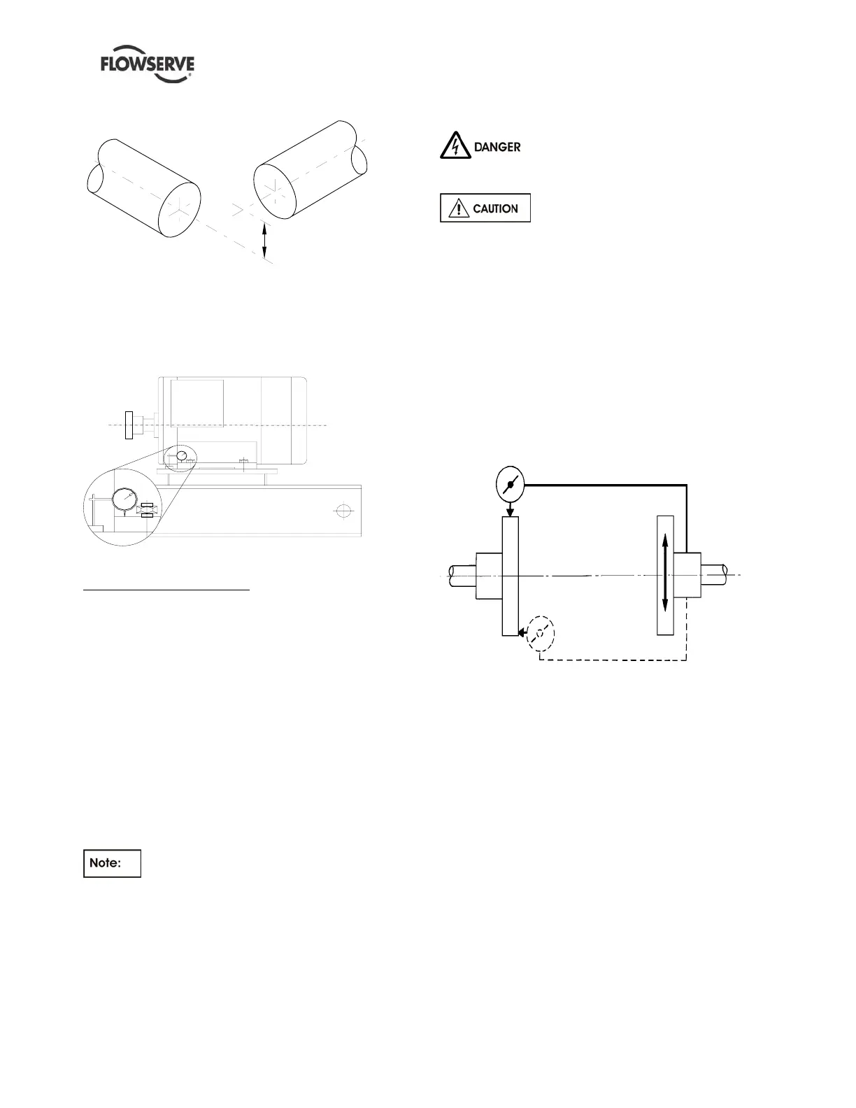
Figure 4.9 – combination of offset and angular misalignment
4.5.2.2 Alignment using the Reverse Alignment
Method
The following practices are recommended when
using the reverse method of alignment. These should
be carried out prior to main alignment.
Figure 4.10
UCHECK FOR SOFT FOOT
This is a check to ensure that there is no undue
stress on the driver holding down bolts; owing to non-
level baseplate or twisting. To check, remove all
shims and clean surfaces and tighten down driver to
the baseplate. Set a dial indicator as shown in sketch
and loosen off the holding down bolt while noting any
deflection reading on the Dial Test Indicator - a
maximum of 0.05 mm ( 0.002 in.) is considered
acceptable but any more will have to be corrected by
adding shims, for example, if the Dial Test Indicator
shows the foot lifting 0.15 mm ( 0.006 in.) then this is
the thickness of shim to be placed under that foot.
Tighten down and repeat the same procedure on all
other feet until all are within tolerance.
If the driver is an electric motor with sleeve
bearings then the magnetic centre at which the rotor
will run must be set. This is usually done by lining up
a groove in the shaft to a pointer fixed to the motor
body (refer to Motor Manufacture’s instructions).
4.5.2.3 Alignment using a graph (Reverse
Alignment)
Ensure pump and driver are isolated
electrically and the half couplings are disconnected.
The alignment MUST be checked.
Although the pump will have been aligned at the
factory it is most likely that this alignment will have
been disturbed during transportation or handling. If
necessary, align the motor to the pump, not the pump
to the motor.
The alignment is achieved by adding or removing
shims under the motor feet and also moving the
motor horizontally as required. In some cases where
the alignment cannot be achieved it will be necessary
to move the pump before recommencing the above
procedure.
For couplings with narrow flanges use a dial indicator
as shown below to check both parallel and angular
alignment.
Parallel
Angu l ar
Figure 4.11
Maximum permissible misalignment at working
temperature:
Parallel 0.05 mm (0.002 in.) TIR
Angular 0.025 mm (0.001 in.) TIR
Pumps with thick flanged non-spacer couplings can
be aligned by using a straight-edge across the
outside diameters of the coupling hubs and
measuring the gap between the machined faces
using feeler gauges, measuring wedge or callipers.
When the electric motor has sleeve bearings it is
necessary to ensure that the motor is aligned to run
on its magnetic centreline.
Refer to the motor manual for details.
 Loading...