Do you have a question about the Flowserve Durco Mark 3 and is the answer not in the manual?
Keep instructions close to product, follow safety requirements.
Legal requirement for machinery to conform to CE directives for market access.
Flowserve not liable for misuse; user assumes responsibility for safe operation.
All rights reserved. Reproduction or transmission without permission is prohibited.
Product selected for purchase order specs. Do not operate beyond specified parameters.
Essential safety information, warnings, and hazard symbols for safe operation.
Explains DANGER, WARNING, CAUTION symbols and their implications.
All personnel involved must be qualified and properly trained.
Actions to prevent injury to personnel and damage to equipment and environment.
Requirements for ATEX environments to ensure explosion protection.
Use equipment in appropriate zones; check driver/pump certification.
Example of ATEX equipment marking and classification.
Ensure temperature class suitability for the hazard zone.
Check against documents for damage/completeness. Report within one month.
Methods for unloading boxes, crates, pallets using fork lifts or slings.
Use crane for loads >25kg, trained personnel. Sling angles and positioning.
Specific method for lifting a bare pump.
Lifting method for these baseplate types.
Lifting method for sets with specific lifting points.
Store in clean, dry location, turn periodically. Max 6 months.
Recycle/dispose environmentally. Handle hazardous substances safely.
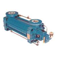
Pump is modular, designed for various chemical liquid pumping requirements.
Explanation of pump size and configuration codes on the nameplate.
Detailed description of key components like casing, impeller, shaft, etc.
Horizontal end inlet, vertical top outlet, self-venting, self-priming option.
Available as reverse vane, open, or recessed types.
Features a large diameter, stiff shaft with a keyed drive end.
Allows for impeller face clearance adjustment via a micrometer mechanism.
Uses ball or roller bearings, lubricated by oil or grease.
Fitted between bearing housing and cover for optimum interchangeability.
Has spigots for improved concentricity between casing and housing.
Seals pumped liquid; gland packing is an optional alternative.
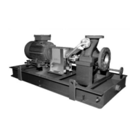
Typically an electric motor; other drive configurations are available.
Standard equipment for temperature and vibration monitoring.
Optional accessories like fan cooling for high-temperature operation.
Typical data for installation, subject to various factors.
Specifies normal maximum/minimum ambient temperatures and maximum pump speed.
Site selection criteria for access, ventilation, and maintenance.
Coupling elements supplied loose; installer responsible for final alignment.
Requirements for mounting on a firm foundation to prevent failure.
Procedure for grouting to ensure solid contact and dampen vibrations.
Align at ambient temperature, accounting for thermal expansion.
Check alignment at operating temperature for high liquid temps.
Detailed steps for checking and correcting shaft alignment.
Procedure to check for undue stress on driver hold-down bolts.
Guidelines for connecting suction, discharge, and auxiliary piping.
Prevent pipe load on flange, flush piping before connection.
Recommendations for pipe sizing and velocity for non-self priming.
Requirements for priming air escape and preventing run-back.
Guidelines for suction pipe layout, diameter, and slope.
Specific recommendations for non-self priming suction piping.
Specific recommendations for self-priming suction piping.
Importance of preventing dirt entry and proper strainer installation.
Recommendations for non-return valves, isolation valves, and regulating valves.
Use of non-return valve to prevent reverse rotation.
Minimizing friction and noise in discharge piping.
Complies with ISO 5199 shaft deflection limits.
Final checks on bolt tightness for pipework and foundation.
Connecting auxiliary piping for flush, quench, etc.
Must be done by qualified electrician, following regulations and manufacturer's instructions.
Recheck alignment after piping is connected and before starting.
Recommended systems for hazardous areas or liquids.
Essential initial checks before commencing operation.
Determining lubrication mode and filling bearings correctly.
Recommendations for suitable oils and greases based on operating conditions.
Table of recommended oils by viscosity and temperature range.
Tables detailing bearing sizes and lubricant capacities.
Guidance on NLGI grades and specific grease types.
Reference to bearing sizes and capacities section.
Reference to maintenance schedule for lubrication intervals.
Initial factory setting and potential adjustments due to temperature.
Critical step to check motor rotation before coupling.
Importance of fitted guards and legal requirements in the EU.
Procedures for priming the pump and connecting auxiliary systems.
Ensuring the pump and casing are completely filled with liquid.
Filling via the designated hole before operation.
Verifying all electrical, hydraulic, and pneumatic systems are ready.
Step-by-step instructions for starting both pump types.
Procedure for starting non-self priming pumps.
Procedure for starting self-priming pumps.
Guidelines for operating the pump once started.
Adjusting gland packing for optimal leakage.
Mechanical seals require no adjustment, run-in procedure.
Monitoring bearing temperatures, especially in potentially explosive atmospheres.
Guidelines for acceptable vibration levels and trip points.
Limits on the number of starts per hour based on motor rating.
Safe procedures for stopping and shutting down the pump.
How changes in operating parameters affect pump performance.
Impact of specific gravity on pump capacity, head, and power.
Effect of liquid viscosity on pump performance and power consumption.
Influence of pump speed on flow, head, power, NPSH, and noise.
Importance of NPSHA margin over NPSHR to prevent cavitation.
Operating within the specified minimum and maximum continuous flow rates.
Operator responsibility for maintenance by qualified, trained personnel.
Recommended plan for routine and periodic inspections and tasks.
Daily/weekly checks on noise, vibration, leaks, lubricant levels.
Checks for foundation bolts, coupling alignment, and wear.
Guidelines for oil and grease lubrication intervals and types.
Intervals for oil changes based on oil type and service conditions.
Intervals for grease application and changes.
When to replace mechanical seals due to leakage.
Procedures for re-packing stuffing boxes.
Information on ordering, storing, and identifying spare parts.
Essential information required when ordering spare parts.
Recommendations for storing spare parts to maintain their condition.
A list of recommended spare parts for a two-year operation period.
Lists standard and specialized tools needed for maintenance.
Table of specified torque values for various fasteners.
Procedure for adjusting impeller clearance after dismantling or for different requirements.
Detailed steps to set clearance for OP impellers.
Detailed steps to set clearance for RV impellers.
Detailed steps to set clearance for recessed impellers.
Safety precautions and steps for dismantling the pump.
Step-by-step guide to disassemble the bearing housing.
Methods for removing both threaded and key drive impellers.
Specific method for removing threaded impellers.
Specific method for removing key drive impellers.
Steps for removing the cover and mechanical seal.
Procedures for disassembling bearing housing components.
Inspecting components after disassembly for wear and damage.
Inspect for wear, pitting, corrosion, and sealing surface irregularities.
Check shaft for runouts and surface condition.
These parts must be discarded and replaced after removal.
It is recommended not to re-use bearings after removal.
Inspect these parts for damage; they are typically non-wearing.
Inspect for damage, contamination, and clear lubrication passages.
General guidance for pump assembly, referring to drawings.
Steps to assemble the bearing housing and rotating shaft components.
Procedures for assembling the seal cover and mechanical seal.
Steps for correctly assembling gland packing and stuffing box.
Procedures for assembling and setting the impeller.
Specific steps for threaded impellers.
Specific steps for key drive impellers.
Steps to fit the power-end assembly into the pump casing.
Diagrams and dimensions for various seal configurations.
Illustrates different types of single mechanical seals.
Diagram of a single seal with an external lip seal.
Illustrations of various cartridge seal configurations.
Diagram of a specific cartridge seal type.
Diagram of a hooked sleeve cartridge seal.
Illustrations of different tandem seal arrangements.
Diagram of a specific tandem seal setup.
Illustrations of double mechanical seal configurations.
Diagram of a double seal arrangement.
Diagrams illustrating external seal configurations.
Diagrams of packed gland seal configurations.
Specific diagram for packed gland with fibre packing.
Lists potential system and mechanical issues leading to pump faults.
System-related causes for pump malfunctions.
Mechanical issues causing pump faults.
Provides solutions and troubleshooting steps for identified faults.
Identifies and addresses electrical issues related to the motor.
Contains sectional drawings and parts lists for the Mark 3 ISO series.
Visual representation of the OP impeller in sectional view.
Enumerates all parts associated with the OP impeller configuration.
Visual representation of the RV impeller in sectional view.
Enumerates all parts associated with the RV impeller configuration.
Drawings and lists for specific pump configurations.
Sectional diagram of the center line mounted configuration.
Parts list for the center line mounted pump casing.
Sectional diagram of the recessed impeller pump.
Parts list for the recessed impeller pump.
Sectional diagram of the self-priming casing pump.
Parts list for the self-priming casing pump.
Provides further specific details on certain components.
Specific information regarding bearing housing seals.
Details pertaining to the OP key drive impeller.
Guides on which parts can be interchanged between models.
Interchangeability matrix for Mark 3 ISO A hydraulic pumps.
Interchangeability matrix for Mark 3 ISO B hydraulic pumps.
Interchangeability for self-priming and recessed impeller pumps.
Information on additional manuals for drivers, seals, etc.
Section for recording agreed product changes after supply.
References to external guides, books, and standards.
| Brand | Flowserve |
|---|---|
| Model | Durco Mark 3 |
| Category | Water Pump |
| Language | English |