DURCO MARK 3 ISO FRAME MOUNTED ENGLISH 85392719 06-12
Page 16 of 52 flowserve.com
e) Fitting an isolation valve will allow easier
maintenance.
f) Never throttle pump on suction side and never
place a valve directly on the pump inlet nozzle.
Suction strainer
4.6.2.3
In a new installation, great care should be taken to
prevent dirt, scale, welding beads and other items
from entering the pump, as it is particularly important
to protect the numerous close running fits from
abrasive matter present in new piping
The suction system should be thoroughly flushed
before installing the suction strainer and making up
suction piping to the pump.
The suction strainer should be installed between 5 to
20 pipe diameters upstream from the pump suction
flange.
The open area of the strainer should
have a minimum of a 3 to 1 ratio to the area of the
pump suction.
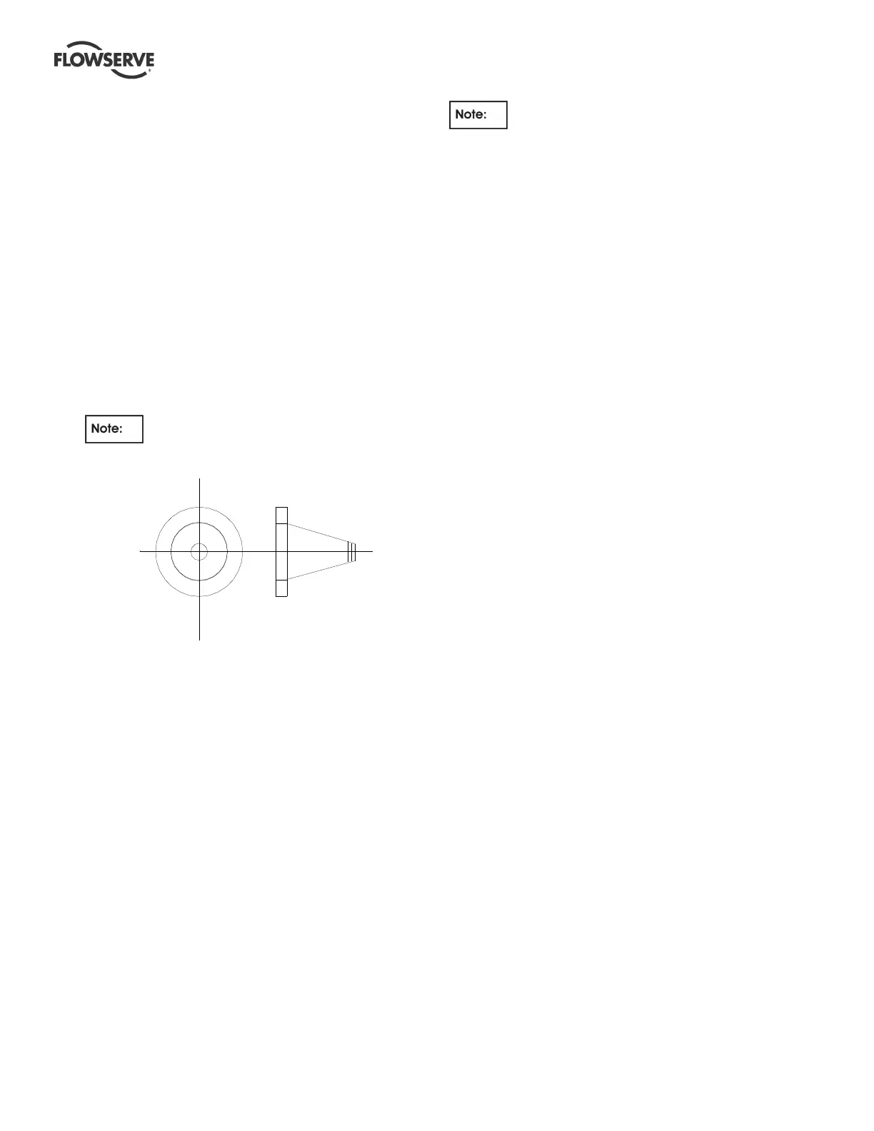
Figure 4.14
Cone Type Strainer
The FLOWSERVE recommendation for suction
strainers consists of a conical shaped steel plate. The
plate has 1.6 mm (1/16 in.) perforations and is of
sufficient size and thickness for the required flow.
See Figure above.
Other type of strainers may be used as long as they
conform to the requirements stated above.
Pressure gauges should be installed on both sides of
the screen so that the pressure drop across the
screen can be measured.
When the unit is being started, the gauges on each
side of the screen should be carefully watched. An
increase in the differential pressure between the two
gauges indicates that the screen is becoming clogged
with dirt and scale. At this point, the pump should be
shut down, and the screen cleaned and/or replaced.
A spool piece should be installed in
suction line so that the suction strainer may be
installed and removed with a pressure gauge
between the strainer and pump.
4.6.3 Discharge piping
Non self-primer casing discharge piping
4.6.3.1
a) A non-return valve should be located in the
discharge pipework to protect the pump from
excessive back pressure and hence reverse
rotation when the unit is stopped.
b) Fitting an isolation valve will allow easier
maintenance.
Self-priming casing discharge piping
4.6.3.2
a) In order to minimize friction losses and hydraulic
noise in the pipework it is good practice to choose
pipework that is one or two sizes larger than the
pump discharge. Typically main pipework velocities
should not exceed 3 m/s (9 ft/sec) on the discharge.
Pipework expanders should have a maximum angle
of divergence of 9 degrees.
b) If a non-return valve is located in the discharge
pipework then a vent/bleed pipe should be fitted
from the discharge pipe back to the sump or
source tank.
c) A regulating valve should be fitted in the discharge
pipework unless pump flow is controlled by the
delivery system design.