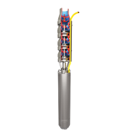
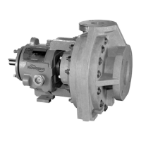
This document provides user instructions for Flowserve DMX/DMXD/DMXH/DMXDH centrifugal pumps, specifically for the BALL/BALL CONFIGURATION. These are multistage, single/double suction, horizontally split volute type centrifugal pumps. The manual covers installation, operation, and maintenance procedures.
Function Description
The DMX/DMXD/DMXH/DMXDH pumps are designed to move liquids at a specified capacity and total head. They are centrifugal pumps, meaning they use a rotating impeller to increase the velocity of a fluid and then convert that velocity into pressure. The multistage design allows for higher heads to be achieved. The single/double suction refers to how the liquid enters the impeller, and the horizontally split volute type describes the casing design, which allows for easier access to internal components. These pumps are selected to meet specific purchaser order specifications and are intended for continuous operation within defined parameters.
Important Technical Specifications
- PCN: 71569282 – 10/09 (E)
- CE Marking and Approvals: The equipment conforms to applicable CE Marking Directives, including Machinery, Low Voltage Equipment, Electromagnetic Compatibility (EMC), Pressure Equipment Directive (PED), and Equipment for Potentially Explosive Atmospheres (ATEX) where applicable. Users should check the serial number plate and certification for specific approvals.
- ATEX Classification: An example marking is II 2 GD c IIB 135 °C (T4), indicating suitability for non-mining (Group II), Category 2 (high level protection), Gas (G) and Dust (D) environments, with constructional safety (c) and a maximum surface temperature of 135 °C (T4). The actual classification is engraved on the nameplate.
- Maximum Surface Temperature: The permissible liquid temperature depends on the ATEX temperature class. For example, a T4 class allows a maximum surface temperature of 135 °C (275 °F) and a liquid temperature limit of 115 °C (239 °F).
- Shaft Alignment Tolerance: Coupling faces must be parallel within 0.0254 mm (0.001 in.) TIR. Coupling outside diameters must be aligned within 0.0762 mm (0.003 in.) TIR. Shaft runout should not exceed 0.050 mm (0.002 in.) TIR.
- Bearing Metal Temperature Set Points:
- Normal: 60 °C to 82 °C (140 °F to 180 °F)
- Alarm: 88 °C (190 °F)
- Shutdown: 93 °C (200 °F)
- Bearing Housing Vibration Set Points:
- Normal: 2.5 to 7.6 mm/s (0.1 to 0.3 in./sec)
- Alarm: 10.2 mm/s (0.4 in./sec)
- Shutdown: 12.7 mm/s (0.5 in./sec)
- Noise Levels: Estimated sound pressure levels (SPL) for 2-stage pumps range from 87 dBA (250-350 BHP) to 94 dBA (above 1500 BHP) at the best efficiency point (BEP). A Part Load Correction (PLC) of +1 to +4 dB must be added if the flow falls outside the 75% to 125% BEP range.
- Grouting: Minimum requirements for epoxy grout include a compressive strength of 12000 psi and a flexural strength of 26.2 Mpa (3800 psi).
Usage Features
- Pre-commissioning: Requires ensuring the pump and piping are clean, flushing the system, cleaning and filling bearing housings with oil, checking oil ring positioning, turning the rotor by hand to ensure free movement, and verifying mechanical seal assembly and tightness.
- Start-up: The discharge valve should be closed (or cracked open if no bypass system is used). The driver must be prepared according to manufacturer instructions. Thermal shocks should be avoided by preheating the pump if necessary, ensuring the casing external temperature is within 55.6 °C (100 °F) of the liquid temperature. A maximum temperature delta of 28 °C (50 °F) between the upper and lower case should be checked.
- Operation: The pump must never be operated with the suction valve closed, unless filled with liquid and vented, or without proper lubrication. Continuous monitoring of suction and discharge pressure gauges, suction strainer pressure differential, leakage, unusual noises, and oil ring rotation is essential. Eye protection is required for certain checks.
- Shutdown: For motor-driven pumps, de-energize the driver circuit. For turbine-driven pumps, manually trip the overspeed trip. If freezing temperatures are a risk, the pump must be drained.
- Protection Systems: Recommended protection systems include devices to prevent running against a closed valve or below minimum continuous safe flow, power monitors to prevent dry running, and leakage detection systems for hazardous liquids. Temperature or vibration monitoring for bearings is also recommended.
- Hot Pumps: For pumps handling liquids at 94 °C (200 °F) and over, the pump support feet must be doweled to the pedestal at the coupling end. A 0.051 mm (0.002 in.) clearance must be established between the self-locking nuts and the pump foot. Gib blocks are used to control horizontal movement, maintaining a 0.254 mm (0.010 in.) gap between the gib block and pump foot.
Maintenance Features
- Safety: Maintenance work should never be performed when the unit is connected to power. Appropriate safety gloves and equipment are required when handling components. Heavy pieces (above 25 kg / 55 lb) require a crane. Coupling guards must remain in place during operation.
- Maintenance Schedule: A maintenance plan and schedule should be adopted.
- Spare Parts: Recommended spares and consumable items are listed.
- Tools Required: Not explicitly detailed but implied for various tasks.
- Fastener Torques: Refer to sectional drawings for specific values.
- Disassembly: Involves removing throttling sleeves, impellers, split rings, and keys. Heating is often required to remove shrunk-fit components like throttling sleeves and impellers.
- Examination of Parts: Includes checking shaft runout, wire-brushing parts for scale/carbon, examining throttling/center/crossover sleeves for wear, and inspecting casing/impeller rings. Worn rings should be replaced as a set.
- Dynamic Balancing: Impellers must be dynamically balanced after any tampering (e.g., new impeller, wear rings installed) using a suitable balancing machine and trained personnel. Two balance planes are used, and metal is removed from impeller shrouds.
- Assembly: All fasteners must be tightened to proper torque values. Bearings require careful handling and installation, often involving heating the inner race for mounting. Impeller rings are installed with set-screws, either axial or radial.