Do you have a question about the Flowserve CS and is the answer not in the manual?
General safety guidance and placement of instructions.
Legal requirement for CE marking directives and approvals.
Information reliability, parts, and accuracy disclaimer.
Reproduction and transmission restrictions for instructions.
Product selection based on purchase order and service conditions.
Explains safety symbols and personnel requirements.
Explanation of safety symbols (Danger, Warning, Caution, Ex).
Requirement for qualified personnel for operation and maintenance.
Conditions and actions to prevent injury and damage.
Specific hazards, operational safety, maintenance safety, and component handling.
Critical safety for specific environments.
Using equipment appropriate for the zone and checking certifications.
Explanation of ATEX equipment marking and classification.
Ensuring equipment temperature class suits the hazard zone.
Ensuring pump is filled, vented, not run dry, and good ventilation.
Coupling guards, earth contact, avoiding static charge.
Using correct liquids, avoiding pressure buildup, monitoring seals.
Using correct tools and materials for maintenance in hazardous areas.
Warning label content about liquid fill and reading instructions.
Performance data supplied separately to the purchaser.
Attention to noise levels, exposure limits, and mitigation.
Checking for completeness and damage upon receipt.
Procedures for unloading boxes, crates, pallets using forklifts or slings.
Safe lifting procedures, personnel qualification, and equipment rigging.
Precautions to protect the pump from deterioration during extended storage.
Methods for applying and removing rust preventive coatings.
Precautions to protect the pump from deterioration during extended storage.
Procedures to prevent deterioration during extended storage.
Considerations for selecting a suitable storage area.
Periodic inspection schedule and methods for stored equipment.
Flowserve representative inspection prior to installation.
Final inspection by Flowserve representative before installation.
Procedures for storing installed and wetted pumps.
General requirements for storing pump drivers.
Environmental guidelines for recycling and disposal of parts.
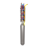
Description of different pump configurations.
Identification of component names and their numbering.
Detailed description of major pump components.
Description of the shaft material, stresses, grinding, and polishing.
Details on stuffing box housings, sealing, and maintenance.
Description of impellers, wear rings, and their mounting.
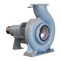
Description of the discharge casing, nozzle, and flange.
Explanation of the axial balance mechanism.
Description of bearing type, lubrication, and angular contact bearings.
Role of pump pedestals in alignment.
Product selection based on purchase order specifications.
Selecting pump location for access, ventilation, and maintenance.
Reading user instructions and related documentation.
General guidelines for foundation design and installation.
Recommended foundation bolt arrangement and installation details.
General considerations and leveling for baseplate installation.
Requirements for foundation rigidity and structural resonance.
Procedure for leveling the baseplate using screws and checks.
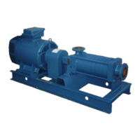
Pump mounting on baseplate and driver mounting.
Pump mounting on baseplate and driver mounting.
Checking for soft feet and allowable foot movement.
Allowing for thermal expansion during alignment.
Critical steps for aligning pump and driver shafts.
Guidelines for shaft alignment according to API standards.
Explanation of angular, offset, and combined misalignment.
Steps for measuring and correcting shaft alignment.
Setting axial gap between pump and driver shafts.
Torquing hold-down bolts and fixing the machine before measuring.
Methods for measuring and adjusting horizontal alignment.
Considering vertical thermal expansion for alignment.
Rechecking parallel and angular alignment of coupling faces and diameters.
Assembling the coupling and installing the guard.
Procedure and form for recording rim and face alignment data.
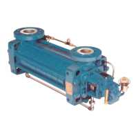
This document provides comprehensive user instructions for the installation, operation, and maintenance of Flowserve Type CS Centrifugal Pumps. These pumps are designed for efficient and reliable service, built with advanced design, proper material selection, and precision construction. The manual emphasizes safety, proper handling, and adherence to specified operating conditions to ensure trouble-free performance and prevent damage or injury.
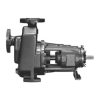
Flowserve Type CS Centrifugal Pumps are designed to move liquids by converting rotational kinetic energy into hydrodynamic energy. These pumps are of the ring section type, meaning they consist of multiple stages assembled in a stacked configuration. The core components include the shaft, impellers, diffusers, and casings, all working together to generate flow and pressure.
The shaft, machined from high-quality material, is designed for low torsion stresses and is accurately ground and polished. Impellers, individually mounted and keyed to the shaft, are responsible for imparting energy to the fluid. Renewable casing wear rings are provided to control leakage past the impeller hubs, maintaining efficiency. The discharge casing serves as the exit port, directing fluid from the last stage diffuser to the pipework and housing the outboard stuffing box.
A key feature of these pumps is the self-compensating flanged balance disc and counter balance disc assembly, which maintains complete axial balance during operation. This balancing device effectively counteracts the normal axial thrust developed by the rotor towards the suction end of the pump, ensuring smooth and stable operation. This design allows for field renewal of the balancing device without disturbing the pipework or the main pump bundle.
The pumps are equipped with stuffing box housings that seal the suction and discharge casings and the shaft. These housings are designed to withstand maximum discharge pressure and can accommodate either packing or various mechanical seals. Water-cooled stuffing box housings are available for higher pumping temperatures, ensuring effective sealing under demanding conditions.
Bearings are typically of the antifriction roller radial type, with grease lubrication as standard, though oil lubrication is optional. For units fitted with an optional rotor setting spring, the non-drive end includes an antifriction single row angular contact ball bearing in addition to the roller type bearing. Pump pedestals are integrated to help maintain alignment of the suction and discharge nozzles when tie bolts are tightened.
The pump is designed for continuous operation within specified parameters. It is crucial to operate the pump within the flow rates, temperatures, and pressures outlined in the purchase order and related documentation to avoid overloading the motor, causing cavitation, reducing pump/bearing life, or leading to instability and vibration.
Proper installation is paramount for optimal performance. This includes selecting an appropriate location with adequate space for access, ventilation, operation, maintenance, and inspection. The foundation must be sufficiently rigid and substantial, typically reinforced concrete, to prevent vibration and support the equipment at all points. Leveling the baseplate and aligning the pump and driver shafts are critical steps, with precise measurements and adjustments required to minimize stresses and ensure smooth operation. The manual provides detailed instructions for both angular and offset alignment, emphasizing the use of dial indicators or laser alignment methods.
During start-up, it is recommended to start the pump with the discharge valve partially opened to minimize the risk of overloading and damage. Inlet valves must be fully open when the pump is running and during start-up. The pump must never be run dry, as this can cause severe damage to the seal.
For pumps operating in potentially explosive atmospheres (ATEX zones), specific precautions must be observed. This includes ensuring the equipment's temperature class is suitable for the hazard zone, preventing excessive surface temperatures, avoiding the build-up of explosive mixtures by ensuring the pump is properly filled and vented, and preventing sparks through non-sparking coupling guards and proper earthing. The pump must only be used with liquids for which it has approved corrosion resistance.
Regular maintenance is essential for ensuring the longevity and reliable operation of Flowserve Type CS Centrifugal Pumps. The manual outlines a comprehensive maintenance schedule, including preventive maintenance, disassembly, rebuilding, and major overhaul procedures.
Lubrication is a critical aspect of maintenance. The bearing housings should be filled with the recommended oil or grease, and the lubrication system should be checked regularly. For mechanical seals, proper filling of seal chambers and auxiliary systems is necessary.
Disassembly and rebuilding instructions are provided, including torque values for various components and a list of required tools. The design allows for servicing of stuffing box housings and renewal of balancing devices in the field without extensive dismantling of the pipework or main pump bundle.
The manual also includes a section on troubleshooting, providing guidance on identifying causes of common faults and their remedies. This helps operators diagnose and resolve issues efficiently, minimizing downtime.
For extended storage periods, specific preservation procedures are detailed to protect the pump from deterioration. This includes applying rust preventives to internal and external machined surfaces, protecting non-machined surfaces with paint, and storing the pump in a protected, vibration-free environment. Periodic inspections during storage are recommended to check for moisture, rust, and material deterioration, with provisions for re-preserving or replacing parts as needed.
At the end of the product's service life, guidelines for recycling and disposal of materials are provided, emphasizing environmentally acceptable methods and compliance with local regulations, especially for hazardous substances.
Overall, the Flowserve Type CS Centrifugal Pump is designed for robust performance, with detailed instructions provided to support its entire lifecycle, from installation and commissioning to ongoing operation and maintenance, ensuring safety and efficiency.
| Type | Centrifugal |
|---|---|
| Application | irrigation |
| Operating Temperature | -20°C to +120°C |
| Impeller Type | Closed or semi-open |
| Casing Material | Cast iron, stainless steel |
| Material | Cast iron, stainless steel |