CS USER INSTRUCTIONS ENGLISH 10.06.77.10986 - 12/05
Page 15 of 66
®
absolute concentricity with all diametric fits
machined at one setting.
3.3.3 Shaft [2100]
The shaft [2100] furnished is machined from the
highest quality material selected with consideration
to the service for which the pump is to be applied.
The shaft is of sufficient diameter to assure low
torsion stresses and is accurately ground and
polished throughout its entire length.
3.3.4 Sealing - Stuffing box housings [4110.’s]
The stuffing box housings [4110.’s] seal the pump
suction and discharge casings [1130 and 1140] and
shaft [2100] and mounts, at their outboard end, the
bearing housing [3200.’s.].
The stuffing box housings [4110.’s] are designed to
withstand the maximum discharge pressure and
accept either packing [4130] or various mechanical
seals [4200].
The stuffing boxes housings [4110.’s] may be
serviced by removing a minimum of parts and may
be removed without disturbing the suction and
discharge piping, tie bolts [6571], or main pump
bundle.
By using a spacer type coupling [7000] the inboard
stuffing box housing [4110.1] can be removed to
allow the inspection of 1
st
stage impeller [2200.1]
and its casing wear ring [1500.1] clearances.
Water-cooled stuffing box housings [4110.’s] are
used for pumping temperature above 130 °C (266
°F) when fitted with mechanical seal [4200] and
above 100 °C (212 °F) when including packing
[4130].
3.3.5 Impellers and wear rings [2200.’s and
1500.’s]
Individually mounted impellers [2200.’s], of one-
piece construction, are keyed to the shaft with
keyways, as standard, on alternate sides of the shaft
[2100]. The 1st stage impeller [2200.1] is positioned
against a shoulder on the shaft [2100] with the
remaining impellers [2200.2] stacked hub to hub.
During operation, force is transmitted through the
impeller [2200.’s] hub into the shaft [2100] at the
shaft [2100] shoulder.
Renewable casing wear rings [1500.’s] are provided
to control leakage past the impeller [2200.’s] hubs.
3.3.6 Discharge casing [1140]
The discharge casing [1140] is the exit port of the
pump, directs the fluid from the last stage diffuser
[1410.2] to the pipe-work and incorporates the
discharge nozzle and its flange. The discharge
casing [1140] closes the discharge end of the casing
and mounts the outboard end stuffing box housing
[4110.2]. The pump outboard end feet and drilling to
receive the pump tie bolts [6571] are also
incorporated into the discharge casing [1140].
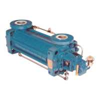
3.3.7 Balancing device [6210 and 6220]
Flowserve ring section pumps are maintained in
complete axial balance during operation by a self-
compensating flanged balance disc [6210], and
counter balance disc [6220]. The balancing device
assembly located at the discharge end effectively
counteracts the normal axial thrust developed by the
rotor toward the suction end of the pump. The front
end of the balance disc [6210] is exposed to full
discharge pressure. The chamber at the back of the
balance disc [6210] is piped to suction pressure,
placing this pressure on the outer face. A thrust is
therefore developed which is equal in magnitude
and opposite in direction to the normal thrust of the
pump impellers [1500.’s] toward the suction.
The pump design allows renewing the balancing
device [6210 and 6220] in the field, without
disturbing the pipe-work, the tie bolts [6571] or the
main pump bundle.
3.3.8 Bearings [3012.’s]
The bearings [3012’.s] are of the antifriction roller
radial type and have grease lubrication as standard
with optional oil lubrication.
In units fitted with optional rotor setting spring [4260]
the non-drive end includes, in addition to the roller
type bearing, an antifriction single row angular
contact balls bearing [3011].
3.3.9 Pump pedestals
The pump should not be removed from the pedestal
unless it is going to be disassembled. The pump
pedestal help to keep the suction and discharge
nozzles aligned while tightening the tie bolts [6571].
3.4 Performance and operating limits
This product has been selected to meet the
specifications of your purchase order; see 1.5.
 Loading...
