CS USER INSTRUCTIONS ENGLISH 10.06.77.10986 - 12/05
Page 20 of 66
®
4.8.3.2 Before alignment
It is recommended that the pump hold
down bolting be torqued and the pump be fixed
before taking any alignment measurements. This
makes the driver [8000] the movable machine. In
certain cases, however, it may be impractical to
move the driver [8000]; therefore, the pump may
have to be moved. When this case exists, the pump
should not be fixed until after final alignment. (See
Doweling Pump and Driver [8000]).
If pump shaft [2100] must be rotated
bearings [3012.’s] and when fitted [3011] are to be
pre-lubed before aligning starts; see 5.3
Align pump and driver [8000] using the rim and face
method, rotating driver [8000] only. Align equipment
such that coupling [7000] hub rims are aligned within
0.050 mm TIR (0.002 in. TIR), and coupling [7000]
hub faces are parallel within 0.025 mm (0.001 in.).
Refer to "RIM AND FACE DATA SHEET";
see 4.11.
Laser alignment, double reverse (dial) alignment, or
reverse rim (dial) alignment methods can be used to
check alignment when site requirements dictate.
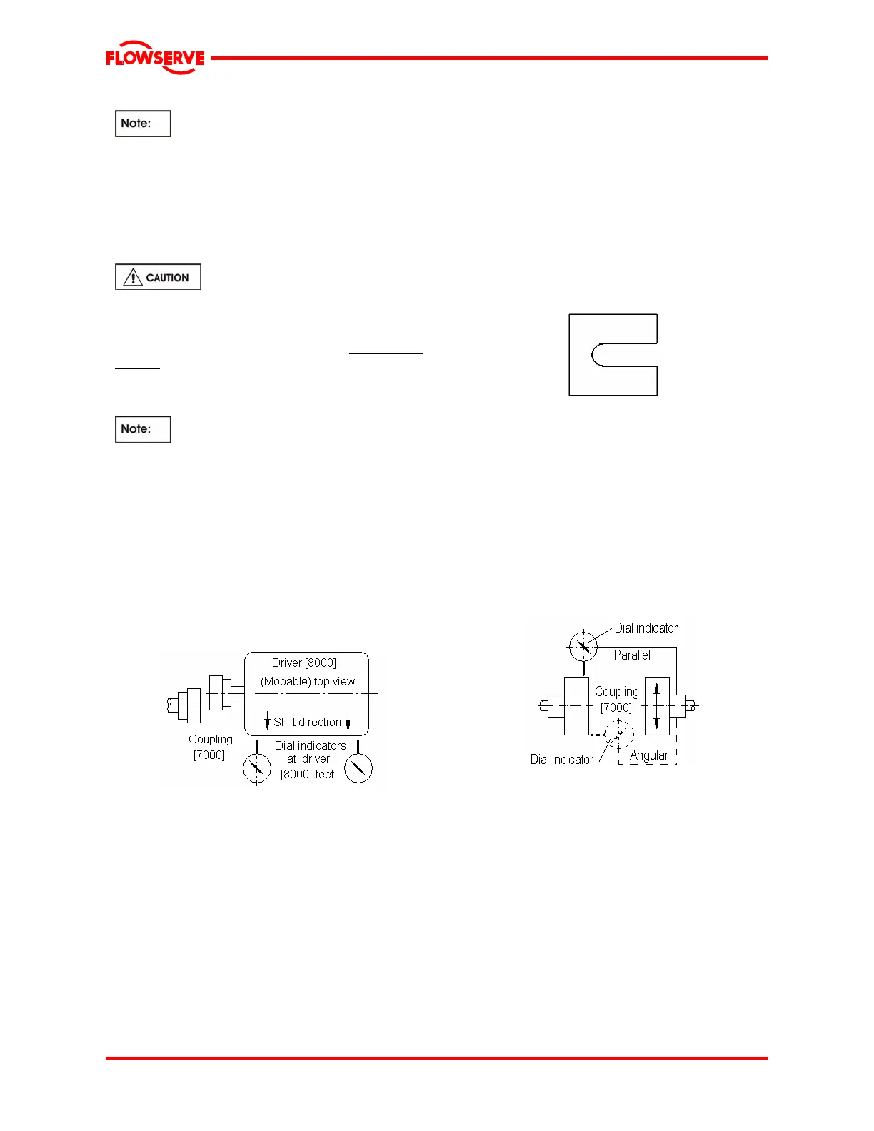
4.8.3.3 Horizontal move
The dial indicators shown below are required to
accurately measure the move in the horizontal
direction. Move the driver [8000] by bumping with
soft hammer/mallet or using the alignment screws (if
provided).
Fig.8 Horizontal Move
4.8.3.4 Vertical move
Before moving the equipment vertically, it is
important that the vertical thermal expansion be
taken into consideration.
Refer to General Arrangement drawing Notes
if any and/or Driver [8000] Instructions for
recommended cold vertical setting.
The stainless steel shims between the equipment
feet and mounting surface should be clean and dry.
This is especially critical for pumps that have been in
service for some time and need to be realigned.
Water, dirt and rust may change the height of the
shim pack over a period of time. Shims should be
made large enough to support the weight of the
equipment on its mounting foot. Do not use many
thin shims, as this may result in a spongy mounting.
Move the equipment vertically by adding or removing
the calculated thickness of shims. Torque equipment
hold-down bolting to required values.
Fig.9 Recommended shim design
4.9 Checking coupling [7000] alignment
The angular and offset coupling [7000] alignment
must now be rechecked:
• Coupling [7000] faces are to be parallel within
0.025 mm (0.001 in.)
• Coupling [7000] outside diameters are to be
aligned within 0.050 mm TIR (0.002 in. TIR)
Use a dial indicator as in Fig.10 to check both
parallel and angular alignment.
Fig.10 Checking coupling [7000] alignment
"Bump" the driver [8000] and check driver [8000]
rotation.
4.10 Assembling coupling [7000]
Assemble the coupling [7000] (s) per the
manufacturer's instructions.
Install coupling [7000] guard(s).