CS USER INSTRUCTIONS ENGLISH 10.06.77.10986 - 12/05
Page 19 of 66
®
Shafts alignment must be correct for
successful operation. Rapid wear, noise, vibration
and actual damage to the equipment may be caused
by shafts misalignment. The shafts must be aligned
within the limits given within this section.
Adjustment to correct the alignment in one
direction may alter the alignment in another direction.
Always check in all directions after making any
adjustment.
Coupled equipment must be aligned to minimize
unnecessary stresses in shafts, bearings and
coupling [7000]. Flexible couplings [7000] will not
compensate for appreciable misalignment.
Foundation settling, thermal expansion or nozzle
loads resulting in foundation deflection and vibration
during operation may require the full coupling [7000]
misalignment capability.
4.8.2 Types of misalignment
There are two types of shafts misalignment: Angular
and Offset. Therefore, two sets of measurements
and corrections are required. Both types of
misalignment can occur in horizontal and vertical
planes and are present in most applications.
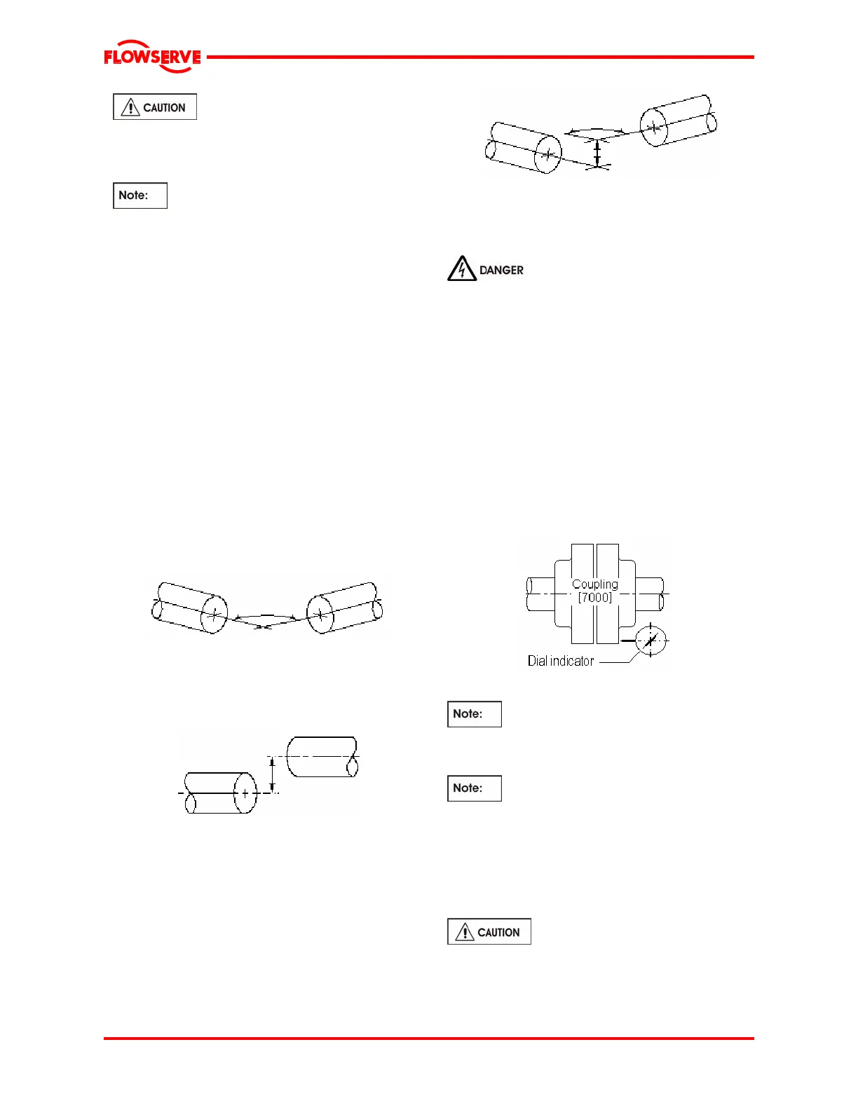
4.8.2.1 Angular misalignment
In angular misalignment, the centerlines of the shafts
intersect, but are not on the same axis; see Fig.4.
Fig.4 Angular misalignment
4.8.2.2 Offset misalignment
In offset misalignment, the shaft centerlines are
parallel but do not intersect; see Fig.5.
Fig.5 Offset misalignment
4.8.2.3 Combination of angular and offset
misalignment
In combined angular and offset misalignment, the
centerlines of the shafts do not intersect, and are not
parallel; see Fig.6.
Fig.6 Combination of angular
and offset misalignment
4.8.3 Alignment
Ensure pump and driver [8000] are
isolated electrically and the coupling [7000] halves
are disconnected.
4.8.3.1 Measure gap
The first step in shafts / coupling [7000] alignment is
to bring the pump and driver [8000] shafts into their
proper axial position. This is done by pulling the
pump shaft [2100] out towards the driver [8000] until
the balance disc [6210] will not permit further
movement. Then with the aid of a Dial Test Indicator
move the shaft [2100] back 0.25mm (0.010 in.). This
sets the shaft [2100] in its correct positive relative to
float position. The driver [8000] is then moved to
attain the desired spacer gap which is shown on the
General Arrangement Drawing to within 0.25mm
(0.010 in.).
Fig.7 Setting axial gap
In units fitted with shaft position indicator
[2920] note and recorder the shaft [2100] axial
position in shaft position indicator [2920] window, see
Fig.20.
If the driver [8000] is an electric motor
[8000] with sleeve bearings then the magnetic center
at which the rotor will run must be set. This is usually
done by lining up a groove in the shaft to a pointer
fixed to the motor [8000] body
Refer to Driver [8000] Manufactures
instructions.
If the driver [8000] does not run in its
magnetic centre the resultant additional axial force
may overload and damage the pump.
Move driver [8000] to insure proper gap distance.