USER INSTRUCTIONS POLYCHEM GRP ENGLISH 71569132 12-04A
Page 27 of 52 flowserve.com
Figure 5-11: Final impeller clearance setting
Pump frame size Impeller gap to casing
Group 1 and 2 0.38 mm (0.015 in.)
3J 8x6G-14 0.51 mm (0.020 in.)
3J 12x10G-15 and 4J 12x10G-15B 0.63 mm (0.025 in.)
The rotation of bearing carrier from center of one lug
on the bearing carrier to center of next lug results in
axial shaft movement of 0.1 mm (0.004 in.).
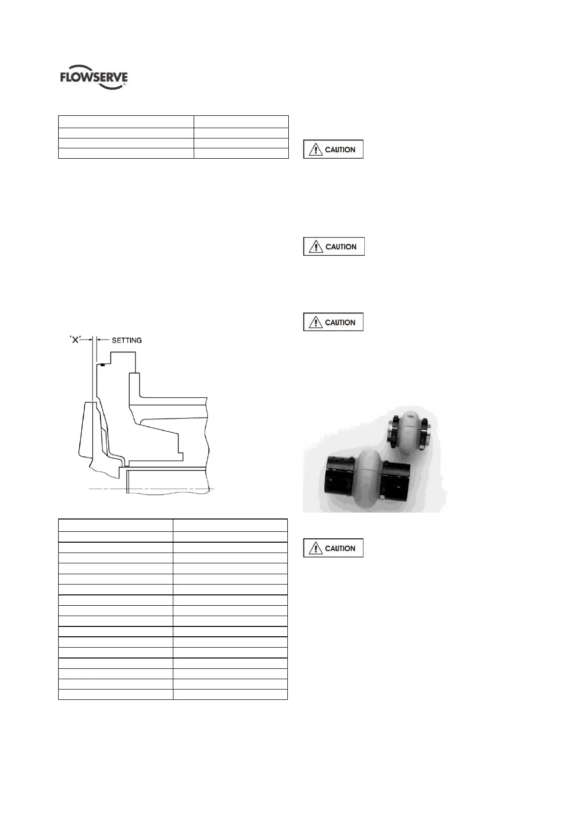
5.3.2 Initial impeller setting
Initial impeller clearance is set off the rear cover since
the casing is typically left in the piping during servicing
of the power end and seal. The initial setting is meant
to get the impeller close to the casing so that final
adjustment does not upset the mechanical seal
setting.Thetabulateddimension“X”(seefig.5-12
and 5-13) can be preset during assembly of the power
end prior to installation into the casing.
Figure 5-12: Initial impeller setting
Figure 5-13:Initialimpellerbacksetting“X”
Pump size Setting distance
1J1k1½ x 1 x 6 3.22 mm (0.127 in.)
1J3 x 1½ x 6 0.91 mm (0.036 in.)
1J3 x 2 x 6K 13.16 mm (0.518 in.)
1J1½ x 1 x 8 0.91 mm (0.036 in.)
2K3 x 1½ x 8 4.16 mm (0.164 in.)
2K3 x 2 x 8 3.17 mm (0.125 in.)
2K4 x 3 x 8 5.51 mm (0.217 in.)
2K2 x 1 x 10 2.36 mm (0.093 in.)
2K3 x 1½ x 10 15.54 mm (0.612 in.)
2K4 x 3 x 10 15.54 mm (0.612 in.)
2K6 x 4 x 10 11.70 mm (0.461 in.)
2K3 x 1½ x 13 0.79 mm (0.031 in.)
2K4 x 3 x 13 0.79 mm (0.031 in.)
3J8 x 6 x 13 1.57 mm (0.062 in.)
3J12 x 10 x 15 17.45 mm (0.687 in)
4J12 x 10 x 15B 17.45 mm (0.687 in)
5.4 Direction of rotation
5.4.1 Rotation check
It is absolutely essential that the
rotation of the motor is checked before connecting
the shaft coupling. Incorrect rotation of the pump, for
even a short time, can dislodge and damage the
impeller, casing, shaft and shaft seal. All PolyChem
GRP pumps turn clockwise as viewed from the motor
end. Make sure the motor rotates in the same
direction.
If maintenance work has been carried
out to the site's electricity supply, the direction of
rotation should be re-checked as above in case the
supply phasing has been altered.
5.4.2 Coupling installation
The coupling (figure 5-14) should be
installed as advised by the coupling manufacturer.
Pumps are shipped without the spacer installed. If
the spacer has been installed to facilitate alignment,
then it must be removed prior to checking rotation.
Remove all protective material from the coupling and
shaft before installing the coupling.
Figure 5-14
5.5 Guarding
Power must never be applied to the
driver when the coupling guard is not installed.
5.5.1 Clam shell guard - standard
The standard coupling guard for all PolyChem pumps is
the“clamshell”designandisshowninfigure5-15. It is
hinged at the top and can be removed by loosening one
of the foot bolts and sliding the support leg out from
under the cap screw. (Note that the foot is slotted).
The leg can then be rotated upward and half of the
guard can be disengaged (unhinged) from the other.
(Note that only one side of the guard needs to be
removed.) To reassemble simply reverse the above
procedure.
 Loading...