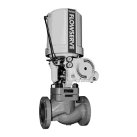
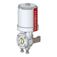
The Valtek VR Spring Cylinder Rotary Actuator is a robust and versatile device designed for precise control in various industrial applications. It combines high torque and pneumatic stiffness with excellent throttling capabilities, making it suitable for both light-weight and rugged applications. The actuator is designed to operate Valtek high-performance butterfly valves, ShearStream V-notch ball valves, and MaxFlo Economy Rotary plug control valves, as well as other applications requiring precise rotary motion.
Function Description
The Valtek VR actuator converts pneumatic pressure into rotary motion to operate quarter-turn valves. It utilizes a spring-cylinder design, where pneumatic pressure acts on a piston to compress a spring, resulting in rotational movement of the valve shaft. The actuator is designed to provide reliable and accurate positioning of the valve, ensuring precise flow control. It can be configured for either fail-close or fail-open air failure operation without changing the fail-safe spring in the actuator, offering flexibility in system design.
Important Technical Specifications
The Valtek VR actuators are designed for supply pressures up to 150 psi (10.3 bar) for sizes VR25, VR50, VR100, and 80 psi for VR200 (5.5 bar), ensuring high torques. The actuator uses a rocking piston for direct conversion of linear motion to rotary motion. The rocking piston assembly, combined with a splined shaft and lever, minimizes lost motion, contributing to the actuator's excellent throttling characteristics.
The actuators are available in various sizes, including 25, 50, 100, and 200 square inches, each with specific minimum overhead clearance requirements for disassembly:
- 25 sq. in.: 6 inches (150 mm)
- 50 sq. in.: 8 inches (200 mm)
- 100, 200 sq. in.: 9 inches (225 mm)
The Valtek VR is designed for use in MODERATE and WORLDWIDE environmental conditions, with ambient temperature ranges from -40°F to 350°F (-40°C to +177°C) and pressures up to 150 psi (10.3 bar) for sizes VR25, VR50, VR100, and 80 psi for VR200 (5.5 bar), unless restricted by accessories. The product offering may include optional ancillary equipment such as positioners, air-filter regulators, solenoid valves, limit switches, or boosters.
The maximum storage time for the diaphragm rotary actuators is 2 years at 25°C.
Usage Features
- Installation: The actuator can be mounted in any position, though vertical mounting of the cylinder is preferred. Adequate overhead and side clearance must be provided for proper removal and maintenance. Air supply and instrument signal lines should be connected to the appropriately marked connections on the positioner. An air filter regulator may be required to ensure the air supply pressure does not exceed the specification sheet's indicated pressure. A soap solution should be used to check for air leaks.
- Lifting and Handling: When lifting the actuator, lifting straps and a hoist should be positioned to avoid damage to tubing and mounted accessories. Caution is advised as the center of gravity may be above the lifting point, requiring support to prevent rotation. A threaded lifting ring hole is provided in the adjusting screw for lifting the actuator using an eye bolt.
- Actuator Action Reversal: The Valtek VR transfer case allows for four different mounting positions and either fail-close or fail-open air failure operation without changing the fail-safe spring. To reverse the actuator action, the adjusting screw should be loosened to relieve spring compression, transfer case cover plate bolts removed, and the cover plate slid off. The linkage bolt on the splined lever arm should be loosened, and bolts connecting the transfer case to the yoke removed. The actuator assembly is then slid off the shaft, and the valve indexed by manually rotating it 90 degrees. The transfer case is then flipped 180 degrees on the yoke. Before reconnecting, verify that the valve rotation matches the actuator rotation and air failure position requirement.
- External Stroke Stops: The actuator features external stroke stops (Stroke Stop Bolt, Item No. 330, and Stroke Stop Jam Nut, Item No. 347) for adjusting the valve's open and closed positions. These adjustments are made by turning the stroke stop bolt and securing it with the jam nut.
- Safety: Users must read all instructions prior to installing, operating, and maintaining the equipment. Hands, hair, and clothing must be kept away from moving parts during operation. The transfer case cover plate and yoke must be mounted before stroking the actuator to prevent damage. Never apply air to the actuator without the cover plate or yoke installed, as the unsupported shaft will sustain damage.
Maintenance Features
- Preventive Maintenance: At least once every six months, the actuator should be checked for proper operation. This includes examining for damage from corrosive fumes or process splatter, cleaning and repainting oxidized areas, stroking the actuator to check for smooth, full-stroke operation, and ensuring the positioner linkage and splined lever arm are securely fastened. A soap solution can be sprayed around the cylinder retaining ring and adjusting screw to check for air leaks.
- Disassembly and Reassembly: The manual provides detailed instructions for disassembling and reassembling the actuator, including steps for removing the spring button, piston, cylinder, and other components. Lubrication of internal parts with silicone lubricant (Dow Corning 55M or equivalent) is crucial during reassembly. The bore that houses the sliding seal assembly in the transfer case must be smooth and clean.
- Troubleshooting: A troubleshooting guide is provided to address common issues such as the actuator operating but the lever arm not rotating, jerky shaft rotation, and high air consumption or leakage. Corrective actions include replacing specific parts (actuator stem, pivot pin, splined lever arm, O-rings), lubricating the cylinder, and checking positioner maintenance instructions.
- Disposal: Up to 95% of the Valtek VR rotary actuator is metal, with the remaining materials being synthetic, rubber, paint, and lubricants. The valve should be professionally disassembled, and metal parts scrapped according to national conditions. Peripheral units (accessories) should be recycled according to the relevant manufacturer's User Instructions. Users must observe national and international environmental conditions for rotary actuator removal from the pipeline and cleaning.