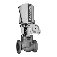
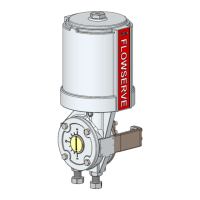
Valtek VR Spring Cylinder Rotary Actuators
VLAIM031-14 (EN/AQ) May 2023
Page 6 of 13
accessories until the actuator is ready for installation at the site.
8. Unpacking
Check the packing list against the materials received.
When lifting the actuator from the shipping container,
position lifting straps and hoist to avoid damage to tubing
and mounted accessories.
When lifting an actuator with lifting
straps, the center of gravity may be
above the lifting point. Therefore, support must be given to
prevent the actuator from rotating. Failure to do so can cause
serious injury to personnel and damage to actuator else
nearby equipment. A threaded lifting ring hole is also
provided in the adjusting screw to insert an eye bolt to lift
only the actuator.
Contact your shipper immediately for any shipping damage.
Contact your Flowserve representative for any problems.
9. Installation
Make sure adequate overhead and side clearance for the actuator
is provided to allow for proper removal and for proper
maintenance. Refer to Table 1.
If the actuator is attached to a Valtek Valdisk,
MaxFlo or ShearStream valve body assembly,
see valve installation, operation, maintenance instructions.
Table 1: Overhead Clearance for Disassembly
Although Valtek VR can be mounted in any
position, mounting the cylinder vertically is the
preferred installation.
Mount the actuator on the desired valve or other mechanical
device.
A sticker can be found on the actuator
cylinder for the maximum air supply
pressure.
The transfer case cover plate and yoke
must be mounted on the actuator prior to
it being stroked, otherwise it will result in damage.
Connect the air supply and instrument signal air lines to the
two appropriately marked connections on the positioner. In
some cases, an air filter regulator must be installed to ensure
the air supply pressure to the pneumatic actuator does not
exceed the pressure indicated on the specification sheet.
The installation of an air filter on the supply line is
recommended.
Use a soap solution to ensure all air connections are free of
leaks.
10. Preventive Maintenance
At least once every six months, check for proper operation by
following the preventive maintenance steps outlined below. These
steps can be performed while the actuator is in service and, in
some cases, without interrupting service.
Keep hands, hair and clothing away
from all moving parts while operating
the actuator. Failure to do so can cause serious injury.
If an internal problem is suspected with the actuator, refer to the
“Disassembly and Reassembly” section.
Examine the actuator for damage caused by corrosive
fumes and process splatter.
Clean actuator and repaint oxidized areas.
If possible, stroke actuator and check for smooth, full-stroke
operation.
Remove the transfer case cover plate and make sure the
positioner linkage and splined lever arm are securely
fastened.
Never apply air to the actuator without
the cover plate or yoke installed;
otherwise, the unsupported shaft will sustain damage. Do
not remove the cover plate when the valve in service or
pressurized.
Be sure all accessories, brackets and bolting are securely
fastened.
If possible, remove air supply and observe the position
indicator plate for correct fail-safe action.
Spray a soap solution around the cylinder retaining ring and
the adjusting screw to check for air leaks through the O-rings.
Actuator Size
(Square inches)
Minimum Clearance
(Inches [mm])
25 6 [150]
50 8 [200]
100, 200 9 [225]