APPENDIX D - TEMP COMP FLUID COMPONENTS INTL
Equipment Required
1 each DC Power Supply, 0 to 20 Vdc minimum, at 0.5 Amps.
2 each 5-1/2 Digit DMM with 4 wire clip leads.
1 each #1 Philips screw driver.
1 each #1 Flat blade screw driver.
1 each Flat screw driver, capable of adjusting control circuit potentiometers.
Insulating varnish or equivalent to reseal the potentiometers.
Procedure
1. Turn off the instrument power.
2. Install the instrument into the pipe or a test stand where it can be calibrated. Start the process media flowing
at a normal rate. Cool the process media to the lowest temperature in the expected operating range.
3. Remove the control circuit. Disconnect the wires on terminals 6 through 10. Removal of the socket from the
enclosure may be necessary for access to the wires.
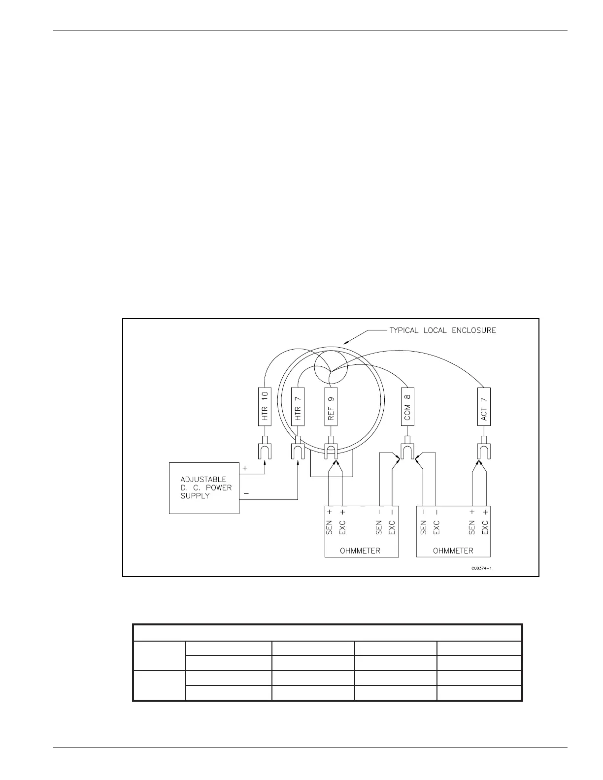
4. Connect the DMM's and the power supply to the sensing element as shown in Figure D-1.
5. Set the power supply voltage to the proper voltage as shown in Table D-1. Turn on the power supply and
check the voltage setting.
Figure D-1. Sensing Element Calibration Connections
Table D-1. Heater Voltage Settings
POWER SUPPLY SETTINGS
FLT93-S
3 Watts 1.75 Watts 0.75 Watts 0.21 Watts
Set For 18.0 Vdc Set For 13.8 Vdc Set For 9.0 Vdc Set For 4.9 Vdc
FLT93-F
0.57 Watts 0.52 Watts 0.40 Watts 0.25 Watts
Set For 18.0 Vdc Set For 17.0 Vdc Set For 15.0 Vdc Set For 11.8 Vdc
Doc. No. 06EN003286 Rev. - D - 3 FLTÔ Series FlexSwitchÔ