FlowCam® 8000 Series Dynamic Imaging Particle Analyzer
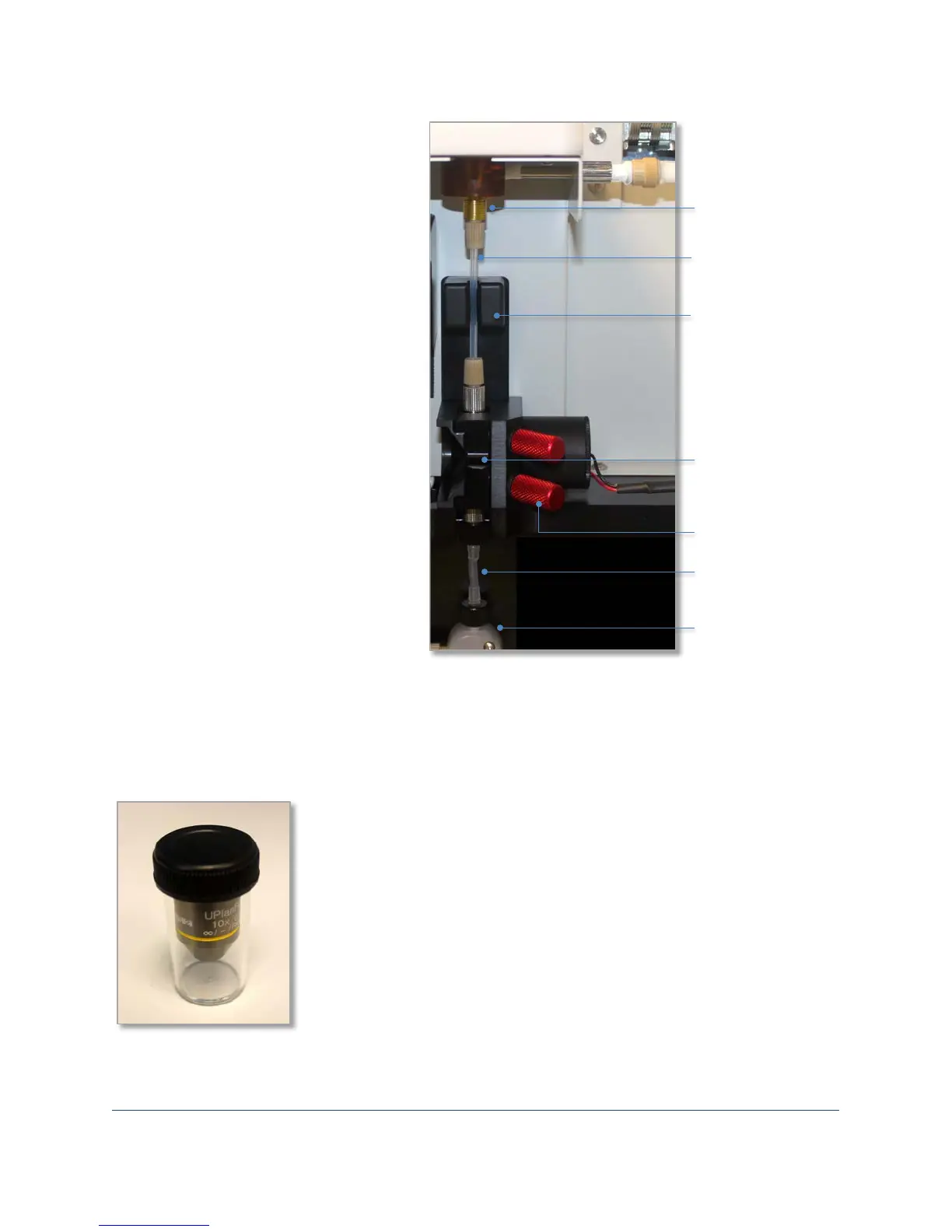
To install the flow cell:
1. Open the upper hatch and lower
door of the FlowCam analyzer.
2. Loosen the flow cell retainer’s two
red thumbscrews and remove it.
3. With the flow cell’s serial number
toward you, connect the upper
tubing attached to the flow cell to
the sample inlet port.
4. Connect the lower tubing attached
to the flow cell to the syringe
pump manifold.
5. Place the flow cell into its
associated opening, and fit the
upper and lower tubing into their
respective slots.
6. Place the flow cell retainer into
the slot so that the flow cell is held
in place and tighten the two
thumbscrews.
7. Close the lower door and upper
hatch.
Installing the Objective Lens
The FlowCam analyzer offers three sizes of objective lenses (4X, 10X and 20X). Depending upon your
particular system configuration, you may have multiple objective lenses.
protective container
inlet port
and retainer
retainer
pump
position
tubing
tubing
 Loading...