EasyManua.ls Logo

Fluidmaster PRO Series - User Manual

Fluidmaster PRO Series
2 pages
To Next Page IconTo Next Page
Loading...
PRO SERIES CISTERN WITH LINK & SEAT
PRO1000A-004 QUICK Install Guide
PARTS OVERVIEWCISTERN TANK OVERVIEW
CONVERTING TO 6/3L OR 9/4.5
FLUSH VOLUME SYSTEM
B1: Remove black cistern tank spacer.
B2: Remove flush valve body & adjust
full and half float settings per Flush
Volume Conversion Table.
B3: Re-install flush valve body and black
cistern tank spacer. Ensure proper
full and half flush alignment.
* Pre-set flush volume settings = 4.5/3L system.
For pairing to a 4.5/3L pan, no flush volume setting adjustment is required.
TOP DOWN VIEW
391mm
420mm
133 mm
A: OPEN LID
B: FLUSH VOLUME CONVERSION
3
2
1
FULL
FLUSH
FULL
FLUSH
HALF
FLUSH
13
1
16
1
A
B
C
C
A
B
Full Float #
Half Float #
Full Window #
4.5/3L 6/3L 9/4.5L
CISTERN FLUSH VOLUME CONVERSION SETTINGS
9.5
12.5
1
5
12
1
1
9
1
A
B
C
C
A
B
Full Float #
Half Float #
Full Window #
4.5/3L 6/3L 9/4.5L
CISTERN FLUSH VOLUME CONVERSION SETTINGS
9.5
12.5
1
5
12
1
1
9
1
A
B
C
FLUSH-LOW LEVEL
WITH LINK.
www.Fluidmaster.com.au
Double Cone Washer
Flush Pipe Wedge Seal
(FM8)
Flush Pipe
Coupling Nut
(FM9)
Link
(FM12)
Seat Bolt (x2)
(FM13)
Seat Nut (x2)
(FM15)
Seat Plate (x2)
(FM14)
Seat with Link Connection Plate (FM11)
Wall Anchor (x2)
(FM6)
Fixed Hole Screw (x2)
(FM5)
NOTE:
(Blue) = Half Flush
(White) = Full Flush
STEP 1: MARK WALL FOR SCREW HOLESPRE-INSTALLATION
STEP 2: SET SCREWS
3mm
Without Wall Anchor
With Wall Anchor
8mm
15mm
Fixed Hole
Screw
(FM5)
Button (Pre-Installed)
(FM1)
FULLHALF
Inlet Valve
(Pre-Installed)
(FM2)
Outlet Valve
(Pre-Installed)
(FM3)
Cistern Plug
(Pre-Installed)
(FM4)
(Blue) (White)
FULLHALF
WALL
TOP OF PAN
FIXED HOLE SCREW LOCATION
356mm
232mm
116mm
FIXED HOLE
247mm
90° Elbow Flush Pipe
(FM10)
Kee-Seal
(FM7)
Question and Answer IconNeed help?

Do you have a question about the Fluidmaster PRO Series and is the answer not in the manual?

Fluidmaster PRO Series Specifications

General IconGeneral
MaterialPlastic
Adjustable HeightYes
Anti-SiphonYes
SeriesPRO Series
TypeFill Valve
CompatibilityMost toilets
InstallationEasy
WarrantyVaries by model

Summary

Cistern Tank Overview

Top Down View

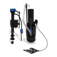
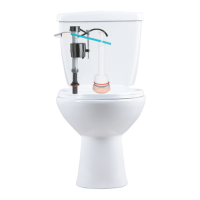
Detailed diagram showing the top view of the cistern tank components.

Parts Overview

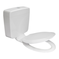
Diagram illustrating the various parts of the cistern system.

Pre-Installation

Open Lid

Instructions on how to open the cistern lid for access.

Flush Volume Conversion

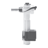
Guide on converting flush volume settings for different water usage.

Convert to 6;3 L or 9;4.5 L Flush Volume System

Details on adjusting flush volumes for 6/3L or 9/4.5L systems.

Step 1: Mark Wall for Screw Holes

Step 2: Set Screws

Step 3: Install Flush Pipes

Trim;Cut Flush Pipe

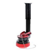
Instructions for trimming or cutting the flush pipe to size.

Connect Flush Pipe to Pan

Lubricate and connect the flush pipe to the toilet pan.

Secure Flush Pipe to Outlet Valve

Attach coupling nut and seal, hand-tightening to connect flush pipe to outlet valve.

Step 4: Hang Cistern Tank

Step 5: Water Supply Connection & Fine-Tune Tank Water Level

Flush Water Supply Line

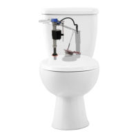
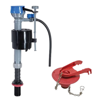
Initial step to turn on water and flush the supply line.

Connect Water Supply to Cistern

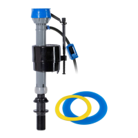
Connect the water supply line to the cistern, hand-tightening fittings.

Check for Leaks

Turn water on again and inspect for any leaks.

Check Tank Water Level

Flush cistern to check water level against the "WL" mark for proper flush.

Step 6: Attach Link (If Required)

Secure Link into Position

Securing the cistern link into its designated position.

Mark Seat Position on Link

Position the seat on the link to mark cut points.

Use Link Cutting Guides

Use cutting lines on the link for necessary adjustments.

Step 7: Install Seat

Insert Seat Bolt Plates

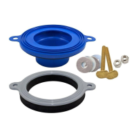
Insert seat bolt plates into the connection plate as guided.

Link Application Seat Installation

Connect link, insert seat bolts, and hand-tighten nuts for link application.

Non-Link Application Seat Installation

Insert seat bolts into pan holes and hand-tighten nuts for non-link application.

Step 8: Attach; Re-secure Lid

Remove and Check Inlet Valve

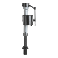
Troubleshooting inlet valve issues by removing and checking for debris.

Troubleshooting & Warnings

Inlet Valve Troubleshooting

Diagnosing and fixing issues like the valve not turning on or off.

Bleach Tablet Warning

Caution against using bleach or chlorine cleaners that can damage components.

Warranty Information

Details on product warranty, exclusions, and claims process.

Cleaning Instructions

Guidance on cleaning the product using soap and warm water.

Related product manuals