Page 37
FW-E115-P-M_v0203_03_EN.docx
4.6.3 TERMINAL S1-S3 – SIGNAL A AND S4-S6 – SIGNAL B; FLOWMETER INPUT
Three basic types of flowmeter signals can be connected to the unit: pulse, active pulse or sine-
wave (coil). The screen of the signal wire must be connected to the common ground terminal (unless
earthed at the sensor itself).
The sensor output of the flowmeter should match with the selected flowmeter input signals at
SETUP 6.1 and SETUP 6.2. See paragraph 3.3.7 for more information.
The connections for Signal A (Terminals S1-S3) and Signal B (Terminals S4-S6) are
identical. In the following paragraphs, where terminals S1-S3 are mentioned in relation to
Signal A, the same is valid for terminals S4-S6 in relation to Signal B.
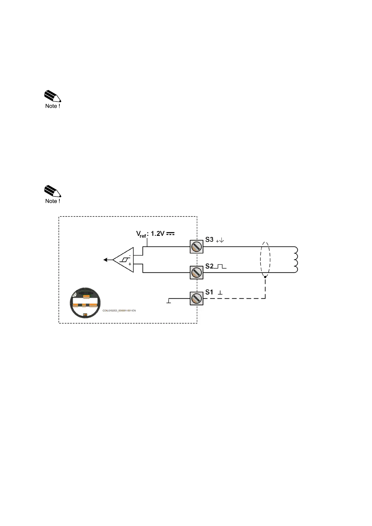
Sine-wave signal (Coil)
The E115-P is suitable for use with flowmeters which have a coil output signal.
Two sensitivity levels can be selected with the SETUP-function:
• COIL LO: sensitivity 90mVpp.
• COIL HI: sensitivity 20mVpp.
• Type ZF offers for setting COIL HI: sensitivity 10mVpp.
• Type ZG offers for setting COIL HI: sensitivity 5mVpp.
When either Signal A or Signal B is configured for COIL HI and the other signal is configured
for COIL LO, both signals will use the COIL HI sensitivity.
Fig. 18: Terminal connections – Coil signal input

 Loading...