Page 16
FW_F130-P_M_v2201-01_EN.docx
The F130-P has two modes: operational or shelf.
After "shelf" has been selected, the F130-P can be stored for several
years; it will not process the sensor signal; the display is switched off
but all settings and totals are stored. In this mode, power consumption
is extremely low.
To wake up the F130-P again, press the START/ key two times.
3.3.7 MENU 6 - FLOWMETER
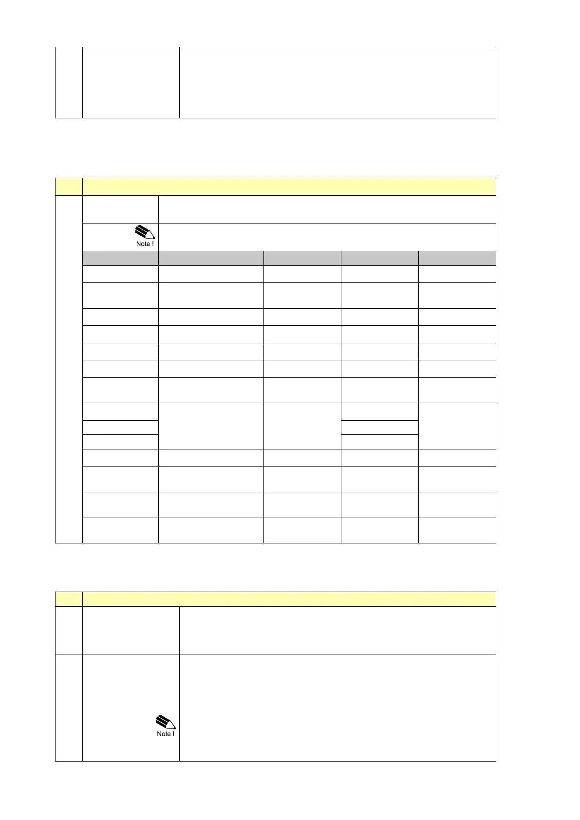
With this setting the type of flowmeter output is selected. The settings with LP (low-pass) filter are
used to apply a build-in noise reduction. Selections "active pulse" offer a detection level of 50% of
the supply voltage.
With this setting the type of flowmeter output is selected. The settings with
LP (low-pass) filter are used to apply a build-in noise reduction.
Selections "active pulse" offer a detection level of 50% of the supply voltage.
(open collector)
less sensitive
Reed-with low pass filter
High sensitive coil input
Sensitive for
interference!
Active pulse input
detection level 8.2 V DC
Active pulse input
detection level 12 V DC
Active pulse input
detection level 24 V DC
3.3.8 MENU 7 - RELAY OUTPUT
Two control outputs are available to control relays or valves. Relay 2 (R2) can also be used as pulse
output according the batch total (actual) or accumulated total.
This submenu is used to set the function of related output.
1-Step: The F132-P is used for one-stage batch control while R2 is
used as a scaled pulse output.
2-Step: The F132-P is used for two-stage batch control.
When Setup 7.1 is set to 2-Step, R2 will be used to control a second
valve for the batch process. Then, the switch-off-moment for R2 has to
be set. The switch moment is based on the remaining quantity before
the end of batch.
If preclose is set to zero, R2 will switch simultaneously with R1.
The settings: width, decimals, amount and pulse are only valid when R2
is used as a scaled pulse output. A scaled pulse output is used to
indicate that the batch or accumulated total has increased with the
value as set in Setup 7.5.